SYSTEM OPERATION
PCIe2-2711 PCI Express Gen2 Expansion System User’s Manual
4-3
Revision 1.1, October 2017
4.4.2
PCIe-436 Mechanical
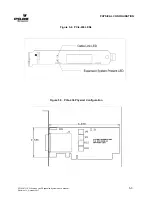
The PCIe-436 has the same outline as a low profile x16 PCI Express add-in card but it is not, it has a
proprietary pin out and should be installed ONLY in slot J10 of the PCIe-460. See Figure 5-4 for a front
panel drawing of the card and Figure 5-5 for a mechanical drawing.
4.4.3
PCIe-436 LED Indicators
The bottom (or left) LED on the front panel is the "Cable Present Detect" LED. This green LED reflects
the status of the "CPRSNT#" signal in the PCIe Expansion Cable. When the LED is ON, it is indicating
that the "CPRSNT#" signal is asserted. The PCIe-460 chassis asserts "CPRSNT#" to indicate that it is
present, the cable is connected and power is good. If this LED is OFF, there may be a problem with
+3.3V power in the expansion chassis or the PCIe Expansion Cable is not connected properly.
The top (or right) LED on the panel is a "PCIe Link Indicator". This yellow LED is
ON solid when all
cable lanes used and are operating at Gen2 rates. A cable link running at Gen1 rates and/or using less
lanes than available will indicate status with a blinking LED. The blinking pattern is the same as the slot
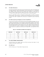
indicators, see Table 4-2.
4.4.4
PCIe-436 Output Swing, De-Emphasis and Receive Equalization
The transceiver silicon used on the PCIe-436 has eight steps of programmable de-emphasis, four steps
of output swing and eight steps of receive equalization. The as-shipped-default configuration of the
transceiver silicon is what Cyclone Microsystems has determined is the best setting for Gen2 operation
with both 1m and 3m PCIe cables shipped with Cyclone PCIe Expansion systems. This configuration
will also function adequately for Gen1 operation.
4.5
LINK INDICATION - LED DEFINITION PCIe-460
The PCIe-460 has eighteen green LEDs to indicate the link status of each slot and the cable. Each slot
and has two redundant LED link status indicators. Ten surface mount LEDs, one for each slot and one
for each cable, are arranged in a row in the corner of the board near J2, see Figure 5-2. The LEDs are
labeled J2, J4, J6, J8, J12, J14, J16, J18 and CABLE.
Eight surface mount LEDs are placed adjacent to each slot. The LEDs are placed just off axis to the
bottom side of an installed board so as not to be obscured by components on the board. The LEDs are
labeled J2 through J18.
A fully functional link (all lanes used and operating at Gen2 rates) will have its LED ON solid. A link
running at Gen1 rates and/or using less lanes than available will indicate status with a blinking LED.
The LEDs indicate link status as follows:

