background image

7

V1.1

the fixture starts to listen to the digital control information sent out from the DMX controller. The allocation 

of this starting address is achieved by setting the correct number on the display located on the base of 

the device.

You can set the same starting address for all fixtures or a group of fixtures, or make different address for

each fixture individually.

If you set the same address, all the units will start to listen to the same control signal from the same 

channel number. In other words, changing the settings of one channel will affect all the fixtures 

simultaneously.

If you set a different address, each unit will start to listen to the channel number you have set, based on 

the quantity of control channels of the unit. That means changing the settings of one channel will affect 

only the selected fixture.

In the case of theFR-40F, which is 1/2/3/4 channels fixture. If you set, for example, the address in the 2 

channel mode to channel 2, the device will use the channel 2 to channel 3 for control.

Note:

 After switching on, the device will automatically detect whether DMX 512 data is received or 

not. If there is data received at the DMX input, the dot in the display will flash.

Universal DMX Control

This function allows you to use a universal DMX-512 controller to control the dimmer and strobe. A DMX 

controller allows you to create unique programs tailored to your individual needs.

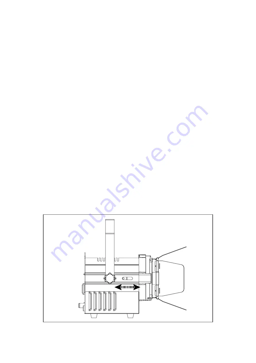
Zoom

This function allows you to adjust the beam width of the fixture.

Step 1: Loosen the zoom buttons on the side of the device.

Step 2: Adjust the zoom by sliding the back lenshousing forward or backward.

Step 3: Tighten the zoom buttons.

Summary of Contents for FR-40F

Page 1: ...USER MANUAL FR 40F RGBW super compact LED fresnel...

Page 2: ...re on a truss 5 Securing with a safety cable 5 DMX 512 connection connection between fixtures 5 Power connection 6 Operation 6 Addressing 6 Universal DMX Control 7 Rotary control 7 Zoom 7 Control Menu...

Page 3: ...f the housing can become hot during operation After use wait for a cool down period of at least 10 minutes before handling or transporting the device Every person involved with the installation operat...

Page 4: ...for indoor use only and must be used in a dry location with adequate ventilation Ensure that none of the fixture s ventilation slots are blocked Fasten the fixture to a secure structure or surface Do...

Page 5: ...ord To clamp the fixture to a truss 1 Check that the rigging structure can support at least 10 times the weight of all fixtures and equipment to be installed on it 2 Block access under the work area 3...

Page 6: ...connected between pins 2 and 3 which is then plugged into the output XLR socket of the last fixture in the chain Caution At the last fixture the DMX cable has to be terminated with a terminator Solder...

Page 7: ...channels of the unit That means changing the settings of one channel will affect only the selected fixture In the case of theFR 40F which is 1 2 3 4 channels fixture If you set for example the addres...

Page 8: ...speed 0 no delay nod 1 Dimmer speed 1 nod 2 Dimmer speed 2 nod 3 Dimmer speed 3 nod 4 Dimmer speed 4 slowest speed Id Id 01 Id 66 ID address setting tEnP 25 100 Fixture temperature UErn Firmware vers...

Page 9: ...be 000 013 Strobe off 014 255 Strobe with speed increasing CH8 Auto program 000 020 no function 021 030 Auto1 031 040 Auto2 041 050 Auto3 051 060 Auto4 061 070 Auto5 071 080 Auto6 081 090 Auto7 091 10...

Page 10: ...els Mode Function Function Control CH1 Red 000 255 0 100 Red dimmer CH2 Green 000 255 0 100 Green dimmer CH3 Blue 000 255 0 100 Blue dimmer CH4 White 000 255 0 100 White dimmer AR2 D 5 Channels Mode F...

Page 11: ...ID12 224 ID35 247 ID58 130 139 ID13 225 ID36 248 ID59 140 149 ID14 226 ID37 249 ID60 150 159 ID15 227 ID38 250 ID61 160 169 ID16 228 ID39 251 ID62 170 179 ID17 229 ID40 252 ID63 180 189 ID18 230 ID41...

Page 12: ...that you may encounter with solutions The fixture does not work no light Check the connection of power and main fuse Be sure the external fuse has not blown Measure the mains voltage on the main conn...

Page 13: ...13 V1 1 www cyclopslighting com...

Reviews: