background image

10

V1.0

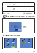
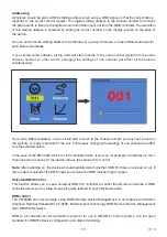
Addressing

All fixtures should be given a DMX starting address when using a DMX signal, so that the correct fixture

responds to the correct control signals. This digital starting address is the channel number from which 

the fixture starts to listen to the digital control information sent out from the DMX controller. The allocation 

of this starting address is achieved by setting the correct number on the display located on the base of 

the device.

You can set the same starting address for all fixtures or a group of fixtures, or make different address for

each fixture individually.

If you set the same address, all the units will start to listen to the same control signal from the same 

channel number. In other words, changing the settings of one channel will affect all the fixtures 

simultaneously.

If you set a different address, each unit will start to listen to the channel number you have set, based on 

the quantity of control channels of the unit. That means changing the settings of one channel will affect 

only the selected fixture.

In the case of the PR-300W, which is 1/2/3 channels fixture. If you set, for example, the address in the 1 

channel mode to channel 2, the device will use the channel 2 for control.

Note: After switching on, the device will automatically detect whether DMX 512 data is received or not. If 

there is data received at the DMX input, you will see the DMX indicator light in green.

Universal DMX Control

This function allows you to use a universal DMX-512 controller to control the dimmer and strobe. A DMX 

controller allows you to create unique programs tailored to your individual needs.

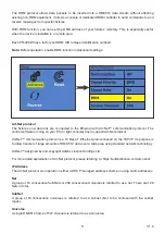
RDM control

The PR-300W can communicate using RDM (Remote Device Management) in accordance with ESTA’s 

American National Standard E1.20-2006: Entertainment Technology RDM Remote Device Management 

Over DMX512 Networks.

RDM is a bi-directional communications protocol for use in DMX512 control systems, it is the open 

standard for DMX512 device configuration and status monitoring.

Summary of Contents for PR-300W

Page 1: ...USER MANUAL PR 300W 300 watts Warm White LED Profile...

Page 2: ...6 DMX 512 connection connection between fixtures 6 Art Net Connection 7 Power connection 7 Operation 8 Control Menu Map 8 Control menu 9 Main Menu 9 Addressing 10 Universal DMX Control 10 RDM control...

Page 3: ...f the housing can become hot during operation After use wait for a cool down period of at least 10 minutes before handling or transporting the device Every person involved with the installation operat...

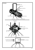
Page 4: ...4 V1 0 Overview...

Page 5: ...l over If you install the fixture in a location where it may cause injury or damage if it falls secure it as directed below with a securely anchored safety cable that will hold the fixture if the prim...

Page 6: ...DMX chain If you wish to connect DMX controllers with other XLR outputs you need to use adapter cables Building a serial DMX chain Connect the DMX output of the first fixture in the DMX chain with th...

Page 7: ...r Requirements The PR 300W luminaire operates on 100 to 240 volts AC 10 auto ranging The luminaire contains an auto ranging power supply Power linking between fixtures The fixture with powercon in and...

Page 8: ...Net Mask for class C IP address Mode DMX 1 2 3CH DMX channel mode ArtNet Net 000 127 Set Art Net net SubNet 000 015 Set Art Net subnet in Art Net net Universe 000 015 Set Art Net universe in Art Net s...

Page 9: ...Timeout 30S Display shut off time Never Screen Brightness 10 100 Display brightness Reset Yes No System reset Reverse Yes No Display reverse 180 degree Control menu The information menu will appear a...

Page 10: ...ave set based on the quantity of control channels of the unit That means changing the settings of one channel will affect only the selected fixture In the case of the PR 300W which is 1 2 3 channels f...

Page 11: ...nning on your PC or light console has to support Art Net protocol Art Net communication protocol is a 10 Base T Ethernet protocol based on the TCP IP Its purpose is to allow transfer of large amounts...

Page 12: ...Rotate the rotary knob to control the dimmer right stop maximum output left stop zero output or strobe right stop maximum strobe left stop no strobe Note Rotary dimmer or strobe function works in inf...

Page 13: ...UP or DOWN button to select Dimmer menu and press ENTER 3 Press DOWN menu and select Mode sub menu 4 Press the UP or DOWN button to select Custom menu and press ENTER 5 Adjust fade in and fade out ti...

Page 14: ...es from the outside of the fixture with low pressure compressed air 3 Clean the surfaces by wiping gently with a soft clean lint free cloth moistened with a weak detergent solution Do not rub glass su...

Page 15: ...snel lens adapter 25 50 PMMA 5 Dimmer curves 16 bit dimmer Strobe Video flicker free with selectable PWM Intelligent temperature control Silent operation Control protocols Rotary DMX RDM Artnet Contro...

Reviews: