background image

AspectFT-Matrix MAX Area Controller Installation Guide 

(1/05/2015)

1-9

1.4.2.3  LED I

NDICATION

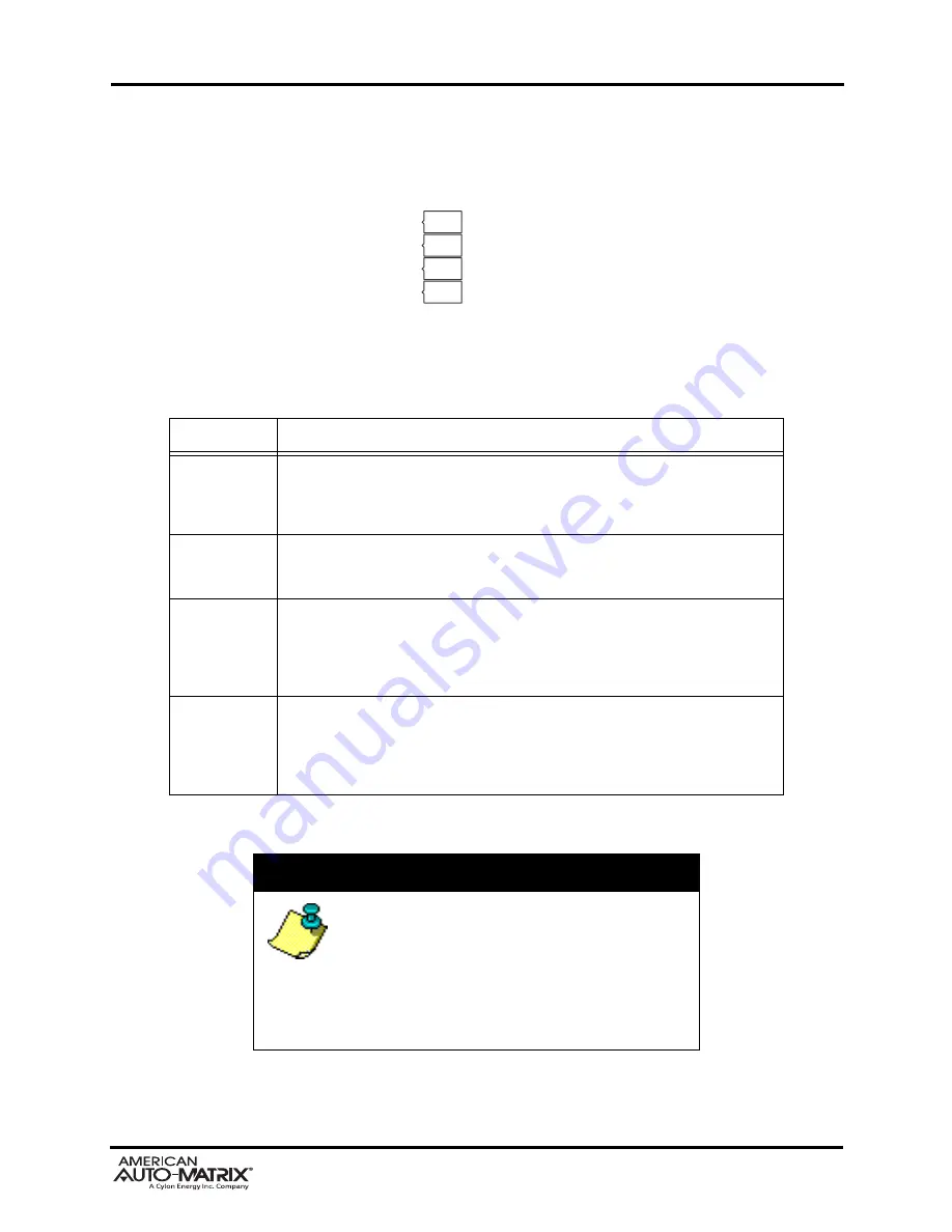
Located below the network termination and biasing switches is a set of diagnostic LEDs that can be useful 
for troubleshooting network communication problems.

TXD

RXD
PERR
BERR

Figure 1-10 Network Diagnostic LEDs

Table 1-1: EIA-485 LED Diagnostics

LED Position

Notes

TXD

This LED will flash anytime data is transmitted by the Matrix Area Controller to 
the field bus network. On an active network, this light should flash anytime the 
device passes a network token to another device or routes a request made by 
another device.

RXD

This LED will flash anytime data is received by the Matrix Area Controller from 
the field bus network. On an active network, this light should flash anytime 
there is activity on the network.

PERR

This LED will flash upon the event a parity error occurs on the network. A parity 
error is caused by a mismatch between the calculated checksum and value 
received with the packet. The most common reason for a packet error is if more 
than one unit is attempting to communicate on the network at once, indicating 
the presence of a duplicate token or duplicate address.

BERR

This LED will flash upon the event a byte error occurs on the field bus network. 
A byte error is caused when information is lost during network communications, 
and is detected in the start, stop, or data bit timings. The most common reason 
for a byte error is due to devices attempting to communicate on the network at 
different baud rates.

NOTE

This product utilizes native EIA-485 
communication drivers.  Therefore, all network 
communications to field-devices should occur over 
specified network media as outlined in American 
Auto-Matrix product documentation.  The use of 
media converters (such as Serial-to-Ethernet 
modems) not certified or sold by AAM is 
discouraged.

Summary of Contents for American Auto-Matrix Aspect Matrix MAX

Page 1: ...Matrix MAX Hardware Installation Guide...

Page 2: ...ctors Drill for mounting the product onto a wall Wire strippers for terminating EIA 485 connections 1 1 2 SAFETY PRECAUTIONS NOTE All equipment must be installed in accordance with NEC and local codes...

Page 3: ...ject Do not handle the printed circuit board PCB without proper protection against static discharge Users should handle PCB components while wearing a ground bracelet or strap connected to Earth groun...

Page 4: ...cation that allows clearance for ease of wiring and service Use the two keyhole style screw holes located on the back of the enclosure for assistance with mounting The product is capable of being moun...

Page 5: ...1 4 AspectFT Matrix MAX Area Controller Installation Guide 1 05 2015 Figure 1 2 AspectFT Matrix MAX enclosure Figure 1 3 Enclosure cover removal...

Page 6: ...out of the product The device includes connection ports for Main Power EIA 485 network connectivity and Ethernet connectivity Depending on the model of Matrix MAX Area Controller you have purchased yo...

Page 7: ...nds using 18AWG cable for power wiring 24VAC Output J1 PWR PWR Figure 1 5 Connecting Power to Matrix MAX Area Controller WARNING Do not share the power source for AspectFT Matrix MAX MAX Area Controll...

Page 8: ...sers communicate with the device for product setup as well as for building automation routines and applications The Ethernet network interface is located on the single board computer card The on board...

Page 9: ...apped or starred 1 4 2 1 CONNECTING EIA 485 NETWORKS Connect the serial network to the determined EIA 485 port Be sure to maintain network polarity at all times Failure to do so can result in loss of...

Page 10: ...will flash upon the event a parity error occurs on the network A parity error is caused by a mismatch between the calculated checksum and value received with the packet The most common reason for a pa...

Page 11: ...ns apply 1 5 2 ETHERNET CONNECTION Termination Count 1 connection Connection Type RJ 45 female Speed 10 100Mb auto sensing 1 5 3 PRODUCT SETUP AND CONFIGURATION Software AspectStudio with USB Copy Pro...

Page 12: ...ce marks or logos contained herein are the property of their respective owners and are only used to describe the product s being listed in this document Every effort has been made to properly capitali...

Reviews: