4
6. OPERATION CONTROLS AND FUNCTIONS
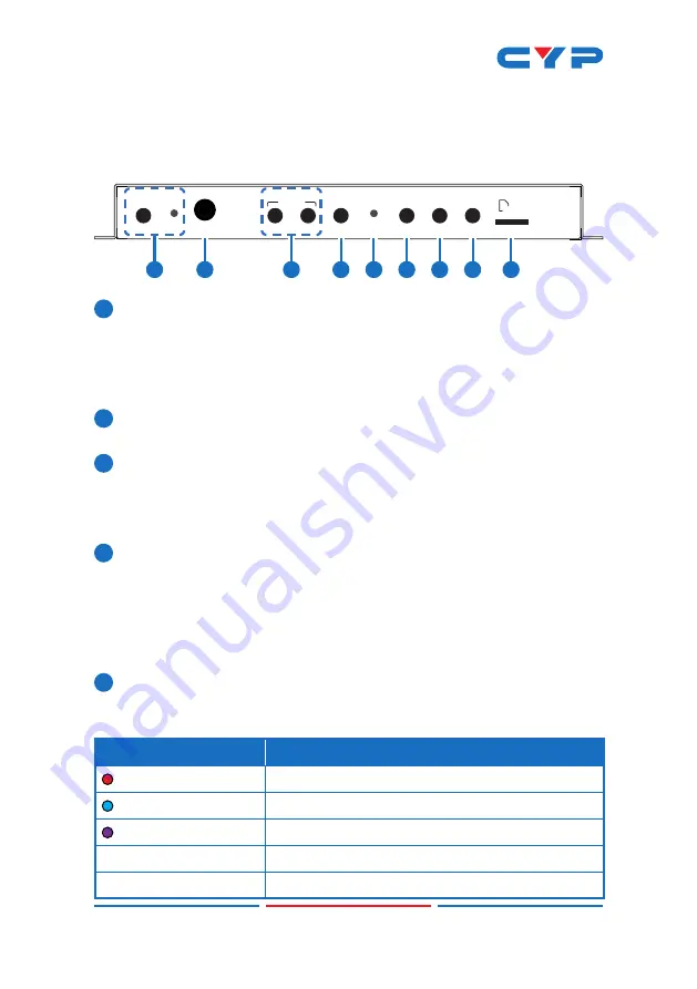
6.1 Front Panel
SELECT
START
POWER
IR
STOP
SOURCE
PLAY
STOP
AUDIO
RECORD
STORAGE
Micro SD
1
2
4
5
6
7
8
9
3
1
POWER Button & LED:
Plug the 5V DC power adapter into this
port and connect it to an AC wall outlet for power. The LED will
illuminate green to indicate the unit is on and receiving power.
When the unit is in stand-by mode the LED will illuminate red.
Note: The Power LED will blink while video recording is active.
2
IR Window:
Accepts IR signals from the included IR remote for
control of this unit only.
3
RECORD START Button:
Press this button to immediately start
recording to the designated recording target.
RECORD STOP Button:
Press this button to immediately stop any
current recording session.
4
SOURCE Button:
Press this button to toggle between the HDMI and
VGA inputs. The status LED will change depending on the input
selection.
Note: Changing the input source will cause the video stream to
restart. Connected stream targets may need to be restarted or
reconnected.
5
Status LED:
This multi-function LED indicates the current video
source selection, audio mixer state and RTMP streaming client
status.
LED State
Description
RED
Video source is VGA
BLUE
Video source is HDMI
PURPLE
Video source is HDMI, Audio Mixer is enabled
Solid (any color)
RTMP streaming client is inactive
Blinking (any color)
RTMP streaming client is active


