8
6. OPERATION CONTROLS AND FUNCTIONS
6.1 Front Panel
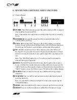
POWER
OUT A
OUT B
IN 1
IN 2
IN 3
IN 4
IN 5
IN 6
MUTE
CONFIRM
CANCEL
ENTER
MENU
PRESET
ALL
INFO
LOCK
+
-
1
2
4
5
7
9
3
6
8
11 13
10 12 14
15
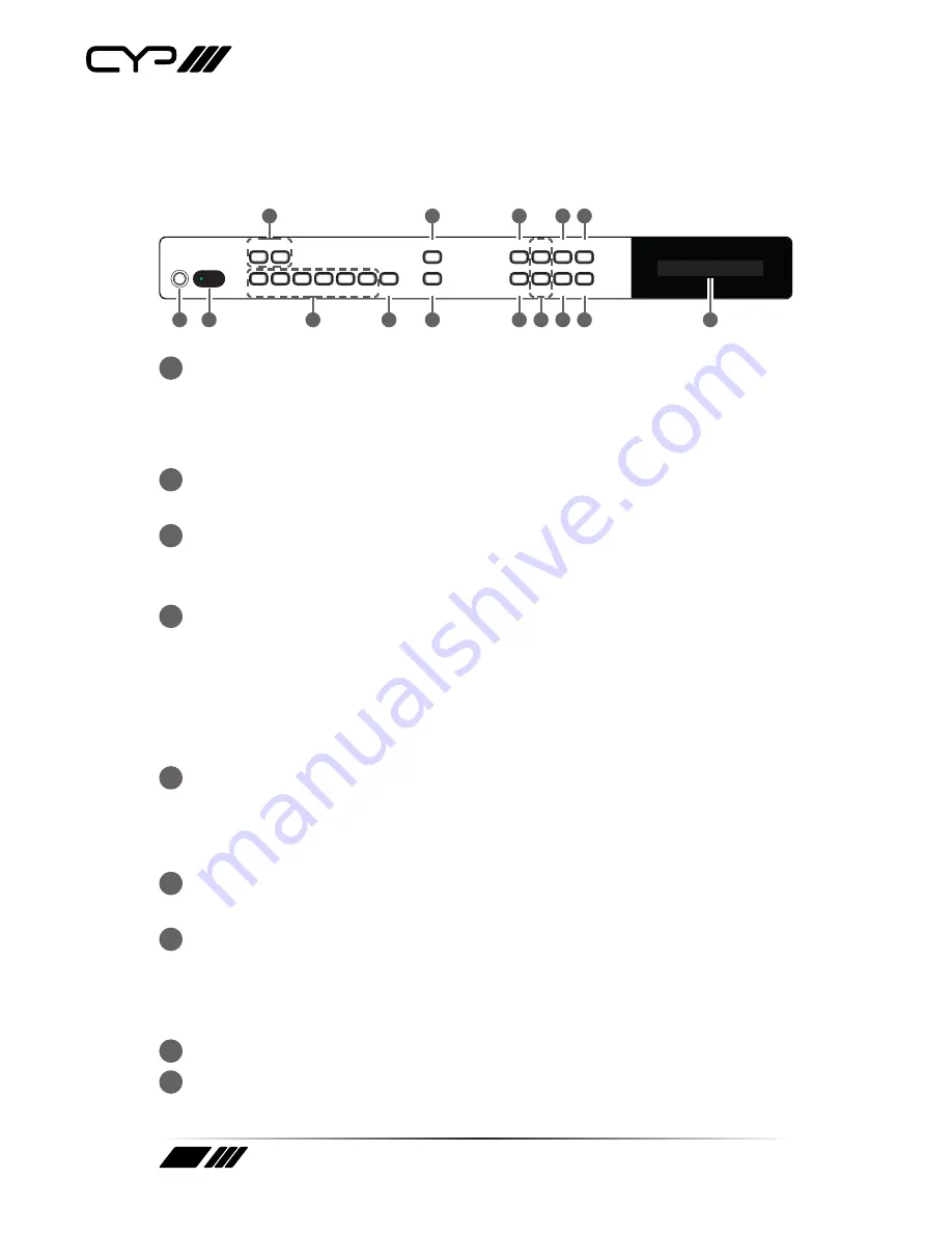
1
POWER:
Press this button to power the unit on (green LED) or place it
into stand-by mode (red LED).
Note: Ethernet, RS-232, and IR remain active while the unit is in stand-by
mode.
2
IR WINDOW:
Accepts IR signals from the included IR remote for
control of this unit only.
3
OUT A~B:
Press the “OUT” keys (A or B) of the outputs you wish to
route a source to (the letter will flash in the LCD to indicate selection).
Pressing an OUT button a second time will de-select that output.
4
IN 1~6:
After selecting one or more outputs, press the “IN” key of
the input (1~6) you wish to route to the selected output(s). In Preset
selection mode, these buttons are used to select the saved preset to
use.
Note: The “CONFIRM” button (Item 7) must be pressed to activate the
selected routing configuration.
5
MUTE:
The “MUTE” button functions as a blank audio/video source.
To use it, follow the standard matrix routing instructions, but use the
“MUTE” button as the input to blank out the selected outputs. When a
“MUTE” input is in use it will show up as “M” within the routing display.
6
CANCEL:
Press to cancel/undo any un-confirmed routing change
selections.
7
CONFIRM:
Press to confirm and activate newly made input/output
routing selections.
Note: It is possible to configure multiple I/O routes prior to pressing the
“CONFIRM” button.
8
MENU:
Press to enter the LCD menu, or to back out from menu items.
9
ENTER:
Press to confirm a selection within the LCD menu or to go


