background image

5

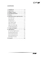
CONTENTS

1. Introduction ...........................................6
2. Applications ...........................................6
3. Package Contents ..................................6
4. System Requirements ...........................7
5. Features ..................................................7
6. Operation Controls and Functions .......9

6.1 Front Panel ................................................... 9
6.2 Rear Panel ...................................................10
6.3 Right Panel .................................................10
6.4 IR Cable Pinouts .......................................11
6.5 RS-232 Control ..........................................12
6.6 RS-232 Commands ..................................13
6.7 EDID Management ..................................15

7. Connection Diagram .......................... 21
8. Specifications ...................................... 22

8.1 Technical Specifications ........................22
8.2 Video Specifications................................23
8.3 Audio Specifications ...............................24
8.4 Cable Specifications ...............................25
8.5 HDBaseT Features ....................................25

9. Acronyms ............................................. 26

Summary of Contents for PUV-1730PLTX-AVLC

Page 1: ...PUV 1730PLTX AVLC HDBaseT HDR Transmitter 70m 4K HDCP2 2 PoH OAR 18Gbps OPERATION MANUAL ...

Page 2: ......

Page 3: ...rves the right to make improvements to this document and or product at any time and without notice COPYRIGHT NOTICE No part of this document may be reproduced transmitted transcribed stored in a retrieval system or any of its part translated into any language or computer file in any form or by any means electronic mechanical magnetic optical chemical manual or otherwise without express written per...

Page 4: ...to this product Never push an object of any kind into this product through any openings or empty slots in the unit as you may damage parts inside the unit Do not attach the power supply cabling to building surfaces Use only the supplied power supply unit PSU Do not use the PSU if it is damaged Do not allow anything to rest on the power cabling or allow any weight to be placed upon it or any person...

Page 5: ... 1 Front Panel 9 6 2 Rear Panel 10 6 3 Right Panel 10 6 4 IR Cable Pinouts 11 6 5 RS 232 Control 12 6 6 RS 232 Commands 13 6 7 EDID Management 15 7 Connection Diagram 21 8 Specifications 22 8 1 Technical Specifications 22 8 2 Video Specifications 23 8 3 Audio Specifications 24 8 4 Cable Specifications 25 8 5 HDBaseT Features 25 9 Acronyms 26 ...

Page 6: ...AVLC Receiver Beyond video data and control this unit also contains useful audio features The Optical Audio Return OAR feature supports transmitting optical audio back from a compatible Receiver for local playback Round ing out the feature set is robust EDID management as well as automatic HDBaseT clock stretching and TMDS re clocking support This Transmit ter PSE can provide 48V PoH Power over HD...

Page 7: ...orts 10 bit and 12 bit HDR High Dynamic Range input output Supports CEC bypass Simultaneous transmission of uncompressed video audio and data over a single Cat 5e 6 7 cable up to 70m 230ft at 1080p60 and 35m 115ft at 4K HDBaseT feature support HD Video and Audio 48V PoH and Control bidirectional IR RS 232 pass through Integrated AVLC Adaptive Visually Lossless Compression activates when the bandwi...

Page 8: ... allows for the uploading of customised user EDIDs via USB Supports HDMI DDC bus clock stretching for improved compatibility with certain Blu ray players Performs TMDS re clocking and signal re generation for improved signal integrity Ultra thin wall plate design 16mm thickness for convenient installation Supports standard 48V PoH from Transmitter PSE to Receiver PD compatible Receivers only ...

Page 9: ...ble Audio is sourced from the Optical Audio Return input on a connected compatible Receiver 4 IR EXTENDER 1 Connect to an IR Extender to extend the IR control range of devices connected to the other end of the HDBaseT connection Ensure that the remote being used is within direct line of sight of the IR Extender 5 IR BLASTER 2 Connect to the provided IR Blaster to transmit IR signals from the other...

Page 10: ...tes that AVLC will use STD Standard mode 3 HQ STD SWITCH This switch allows the user to select which compression mode to use when AVLC is active High Quality or Standard Note HQ High Quality mode uses the least amount of compression and provides the highest possible visual quality perceptually identical to the original STD Standard Quality mode applies additional signal reduction methods to lower ...

Page 11: ...ctions across 3 different operation modes The three modes are Internal EDID User EDID and External EDID There are a total of 6 built in internal EDIDs and 9 User EDIDs which can be modified via USB upload The External EDID setting will copy the EDID from the sink that is connected to the Receiver See EDID Management for more details 6 4 IR Cable Pinouts 3 1 2 Infrared Power Ground IR Extender 3 1 ...

Page 12: ... 232 Control Terminal Block Controlling PC Serial Port Settings Pin Definition Pin Definition Baud Rate 19200 1 GND 1 Data Bits 8 2 Rx 2 Rx Parity Bit None 3 Tx 3 Tx Stop Bits 1 4 Flow Control None 5 GND 6 7 8 9 ...

Page 13: ...T MODEL NAME Show the unit s model name GET MODEL TYPE Show the unit s model type GET POWER Show the power state of the unit SET SYSTEM REBOOT Reboot the unit GET IN 1 SYNC STATUS Show the current input sync state GET OUT A SYNC STATUS Show the current output sync state GET IN 1 EDID Show the input s current EDID source GET IN EDID LIST List all available EDID selections ...

Page 14: ...N1 Set the AVLC compression mode to use Available values for N1 1 High quality 2 Standard quality GET TRANSCEIVER COMPRESS RATE Show the current AVLC compression mode Note Commands will not be executed unless followed by a carriage return Commands are not case sensitive ...

Page 15: ...switches there are a total of 16 possible EDID selections across 3 different operation modes 1 Dipswitch in on down position 0 Dipswitch in off up position ON 1 2 3 4 0 1 EDID Mode Number EDID Number Dipswitch Position Internal EDID 1 1 1111 2 2 1110 3 3 1101 4 4 1100 5 5 1011 6 6 1010 User EDID 1 7 1001 2 8 1000 3 9 0111 4 10 0110 5 11 0101 6 12 0100 7 13 0011 8 14 0010 9 15 0001 Native EDID 16 0...

Page 16: ...0p 30Hz 8 bit LPCM 2 0 297MHz UHD Multi channel 3840 2160p 30Hz 8 bit LPCM 7 1 Bitstream 297MHz UHD 2 channel 3840 2160p 60Hz up to 12 bit LPCM 2 0 594MHz UHD Multi channel 3840 2160p 60Hz up to 12 bit LPCM 7 1 Bitstream 594MHz User EDID 1 9 There are a total of 9 User EDID slots which can be modified via USB upload By default these slots all contain the same standard EDID EDID Video Content Audio...

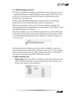
Page 17: ...n Next install the EDID Management software After the installation has successfully completed an icon for it will appear on the windows desktop Launch the software by double clicking on the icon and the EDID Management device detection window will open up on your screen After launching the software power the unit on and then connect it to the PC laptop using a Mini USB to USB cable Click on the Se...

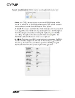
Page 18: ...uploaded into any of the User EDID slots by selecting the User EDID to replace from the dropdown and then clicking the Upload icon Before accepting the upload the software will check and verify that the EDID s header and checksum values are acceptable Analysis To analyze any EDID stored within the unit select the EDID to view from the dropdown and click on the Analysis icon From the Analyser windo...

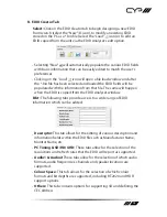
Page 19: ...same will happen when the EDID is copied from the EDID Analyser window Edit The following tabs provide access to a wide range of EDID information which can be edited Descriptor This tab allows for the editing of various description and information fields within the EDID file such as Manufacturer Name Monitor Name etc PC Timing SD HD UHD These tabs allow for the selection of the resolutions and ref...

Page 20: ...irectly to the unit using the Save and Upload icons respectively C System Tab Configuration Firmware Select the System tab to edit the unit s description select the Rename icon to reset the unit to factory defaults select the Reset icon and to view the unit s current hardware and firmware version information ...

Page 21: ...PASS RX RS 232 SERVICE IR OUT OPT IN CAT5e 6 7 IN HQ STD HDMI OUT POWER LINK TX 7m 3m 3m 60 1 5m 60 1 5m 60 7m 3m 3m 60 Game Console UHDTV w Optical Audio Output RS 232 Controlled Device Power Supply Router RS 232 RS 232 USB RS 232 Equipped PC Laptop HDMI Input HDMI Output Cat 5e 6 7 Cable Optical Audio Retun OAR IR In Out IR In Out Optical Audio Return OAR AV Receiver ...

Page 22: ...lock IR Frequency 30 50kHz 30 60kHz under ideal conditions Baud Rate Up to 115200bps Power Supply 48V 0 83A DC US EU standards CE FCC UL certified ESD Protection Human Body Model 8kV Air Discharge 4kV Contact Discharge Dimensions 163mm 16mm 78mm W H D Case Only 183mm 16mm 81mm W H D All Inclusive Weight 200g Chassis Material Aluminum Silkscreen Colour Black Operating Temperature 0 C 40 C 32 F 104 ...

Page 23: ...0 72 75 85 720 400 70 85 800 600 56 60 72 75 85 1024 768 60 70 75 85 1152 864 75 1280 720 50 60 1280 768 60 75 85 1280 800 60 60 RB 1280 960 60 1280 1024 60 1360 768 60 1366 768 60 1400 1050 60 60 RB 1440 900 60 60 RB 1600 900 60 1600 1200 60 1680 1050 60 60 RB 1920 1080 60 1920 1200 60 60 RB ...

Page 24: ...20 1080i 50 59 94 60 1920 1080p 50 59 94 60 1920 1080p 23 97 24 25 29 97 30 3840 2160p 24 25 30 4096 2160p 24 25 30 3840 2160p YUV 4 2 0 50 60 3840 2160p 24 25 30 10 12 bit HDR AVLC 3840 2160p YUV 4 2 0 50 60 10 12 bit HDR AVLC 3840 2160p 50 60 AVLC 8 3 Audio Specifications Digital S PDIF Output Sampling Rate kHz 32 44 1 48 88 2 96 176 4 192 ...

Page 25: ... 12 bit colour Data rates lower than 5 3Gbps or below 225MHz TMDS clock Ultra HD Video 4K 4K 24 25 30Hz 4K 50 60Hz YUV 4 2 0 8 bit colour 4K 50 60Hz 4 4 4 8 bit with AVLC active Data rates higher than 5 3Gbps or above 225MHz TMDS clock 8 5 HDBaseT Features HDBaseT Feature Supported Video Audio IR Pass through RS 232 Pass through Accept power from Receiver Send power to Receiver LAN Pass through ...

Page 26: ...dentification Data HD High Definition HDCP High bandwidth Digital Content Protection HDMI High Definition Multimedia Interface HDR High Dynamic Range IR Infrared LPCM Linear Pulse Code Modulation OAR Optical Audio Return PC Personal Computer PD Powered Device PoH Power over HDBaseT PSE Power Sourcing Equipment S PDIF Sony Philips Digital Interface Format UHD Ultra High Definition UHDTV Ultra High ...

Page 27: ......

Page 28: ...CYP UK Ltd Unit 7 Shepperton Business Park Govett Avenue Shepperton Middlesex TW17 8BA Tel 44 0 20 3137 9180 Fax 44 0 20 3137 6279 Email sales cypeurope com www cypeurope com v1 00 ...

Reviews: