background image

4

SAFETY PRECAUTIONS

Please read all instructions before attempting to unpack, install or operate 

this equipment and before connecting the power supply.

Please keep the following in mind as you unpack and install this 

equipment:

• 

Always follow basic safety precautions to reduce the risk of fire, 

electrical shock and injury to persons.

• 

To prevent fire or shock hazard, do not expose the unit to rain, 

moisture or install this product near water.

• 

Never spill liquid of any kind on or into this product.

• 

Never push an object of any kind into this product through any  

openings or empty slots in the unit, as you may damage parts inside 

the unit.

• 

Do not attach the power supply cabling to building surfaces.

• 

Use only the supplied power supply unit (PSU). Do not use the PSU if 

it is damaged.

• 

Do not allow anything to rest on the power cabling or allow any 

weight to be placed upon it or any person walk on it.

• 

To protect the unit from overheating, do not block any vents or 

openings in the unit housing that provide ventilation and allow for 

sufficient space for air to circulate around the unit.

REVISION HISTORY

VERSION NO.

DATE

SUMMARY OF CHANGE

v1.00

25/07/2019

First release

Summary of Contents for PUV-1H4HPL-AVLC

Page 1: ...PUV 1H4HPL AVLC 1x4 HDBaseT Splitter with AVLC OPERATION MANUAL ...

Page 2: ......

Page 3: ...d reserves the right to make improvements to this document and or product at any time and without notice COPYRIGHT NOTICE No part of this document may be reproduced transmitted transcribed stored in a retrieval system or any of its part translated into any language or computer file in any form or by any means electronic mechanical magnetic optical chemical manual or otherwise without express writt...

Page 4: ...to this product Never push an object of any kind into this product through any openings or empty slots in the unit as you may damage parts inside the unit Do not attach the power supply cabling to building surfaces Use only the supplied power supply unit PSU Do not use the PSU if it is damaged Do not allow anything to rest on the power cabling or allow any weight to be placed upon it or any person...

Page 5: ...ons 9 6 1 Front Panel 9 6 2 Rear Panel 10 6 3 IR Cable Pinouts 11 6 4 RS 232 Pinout and Defaults 11 6 5 OSD Menu 12 6 6 RS 232 Commands 23 7 Connection Diagram 35 8 Specifications 36 8 1 Technical Specifications 36 8 2 Video Specifications 37 8 3 Audio Specifications 39 8 4 Cable Specifications 40 8 5 HDBaseT Features 41 9 Acronyms 42 ...

Page 6: ... can t support AVLC 4K 60Hz RGB YUV 4 4 4 signals will be converted to YUV 4 2 0 or downscaled to 1080p based on the detected EDID on each output This unit provides solid audio support including bypassing 8 channel LPCM digital audio as well as advanced Bitstream and HD Bitstream audio formats via HDBaseT and HDMI Additionally an analogue stereo audio breakout output is available to provide audio ...

Page 7: ...UHD 18Gbps 4K 50 60Hz 4 4 4 8 bit video input and output Note Support of resolutions requiring bandwidth above 10 2Gbps via HDBaseT requires a compatible AVLC receiver Supports Deep Colour input and output up to 12 bit Supports 10 bit and 12 bit HDR High Dynamic Range input output HDBaseT output transmits video audio and data over a single Cat 5e 6 7 cable and can reach distances up to 40m 131ft a...

Page 8: ...ty DAC Digital to Analogue audio Conversion with local analogue stereo audio breakout LPCM 2 0 sources only Comprehensive EDID management options Supports standard PoH from the unit to connected HDBaseT receivers compatible receivers only Note The PoH function is designed for powering compatible Receiver units only Non PoH Receivers will need their own power supply Receivers from other brands may ...

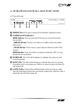
Page 9: ...PLUS Button Press to move up or adjust selections within OSD menus ENTER Button Press to confirm a selection within the OSD or to go deeper into a menu item 3 POWER LED This LED will illuminate to indicate the unit is on and receiving power 4 INPUT LED This LED will illuminate to indicate that a live source has been detected on the input port When no source is detected the LED will remain off 5 OU...

Page 10: ...ender to receive local IR control signals and extend them to devices connected to the other end of all HDBaseT connections Ensure that the remote being used is within direct line of sight of the IR Extender IR OUT Port Connect to the provided IR Blaster to transmit IR signals from the other end of the HDBaseT connection to devices within direct line of sight of the IR Blaster Note To help avoid po...

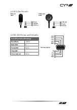
Page 11: ...r Not Used IR Extender Cable 1 2 3 Infrared Power Ground 6 4 RS 232 Pinout and Defaults Serial Port Default Settings Baud Rate 19200 Data Bits 8 Parity Bits None Stop Bits 1 Flow Control None 1 2 3 4 5 8 7 6 9 DCD RxD TxD DTR GND RI CTS RTS DSR DE 9 Female Port ...

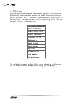
Page 12: ...the OSD menu Press the MENU button to back out from any menu item and then press it again to close the menu MAIN MENU Input Information Output 4K Converter Output Information L R Audio Control EDID Control HDCP Control RS232 Control IR Control Remote Control OSD Setting System Setting The individual functions of the OSD will be introduced in the following section Items marked in BOLD are the facto...

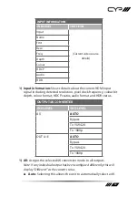
Page 13: ...k frequency colour bit depth colour format HDCP status audio format and HDR status OUTPUT 4K CONVERTER 2ND LEVEL 3RD LEVEL All AUTO Bypass To YUV420 To 1080p OUT A E AUTO Bypass To YUV420 To 1080p 1 All Assigns the selected 4K conversion mode to all outputs Note If any individual output has been configured differently this will display Different as the current status Auto Selecting this allows the...

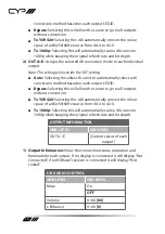
Page 14: ... select a 4K conversion method based on each output s EDID Bypass Selecting this will allow the source to go to all outputs without conversion To YUV420 Selecting this will automatically convert the colour space of a 4K 50 60Hz source from 4 4 4 to 4 2 0 To 1080p Selecting this will automatically scale a 4K source to 1080p while keeping the original refresh rate and bit depth OUTPUT INFORMATION 2N...

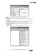
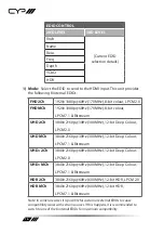
Page 15: ... in 0 5 dB steps 3 L R Enhance Independently increase the output volume of the left or right channel of the analogue audio output in 0 5 dB steps 4 Audio Details Block Shows detailed information about the current audio signal Note Some information is not available with bitstream sources EDID CONTROL 2ND LEVEL 3RD LEVEL Mode INT FHD 2CH Int FHD MCh Int UHD 2Ch Int UHD MCh Int UHD 2Ch Int UHD MCh In...

Page 16: ...bit Deep Colour LPCM 2 0 UHD MCh 3840 2160p 30Hz 300MHz 12 bit Deep Colour LPCM 7 1 Bitstream UHD 2Ch 3840 2160p 60Hz 600MHz 12 bit Deep Colour LPCM 2 0 UHD MCh 3840 2160p 60Hz 600MHz 12 bit Deep Colour LPCM 7 1 Bitstream HDR 2Ch 3840 2160p 60Hz 600MHz 12 bit HDR LPCM 2 0 HDR MCh 3840 2160p 60Hz 600MHz 12 bit HDR LPCM 7 1 Bitstream Note In some rare cases it is possible for custom or external EDID...

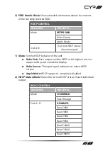
Page 17: ...r of the unit Refer Sink Each output enables HDCP at the highest version supported by each connected display Refer Source The input signal maintains its native HDCP version Apple Mode HDCP support is completely disabled 2 HDCP Status Block Shows the current HDCP status of each individual output RS232 CONTROL 2ND LEVEL 3RD LEVEL Mode COMMAND Pass Through Port A D DISABLED Baud 2400 Baud 4800 Baud 7...

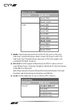
Page 18: ...ough allows extension of RS 232 signals to all connected HDBaseT receivers 2 Port A D Set the supported baud rate for RS 232 extension over each HDBaseT port Selecting Disabled will block RS 232 from being extended over that port Note Baud rate conversion will be performed automatically if the local baud rate and destination port baud rate are different 3 Local Set the baud rate to use on the loca...

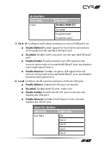
Page 19: ... to the specified HDBaseT port but disables receiving IR signals from it Enable Receiver Enables reception of IR signals from the receiver connected to the specified HDBaseT port but disables transmitting IR signals to it 2 Local Configure the IR extension behavior of the local IR ports Enable Bidirect Enables both IR ports on the unit Disabled Disables both IR ports on the unit Enable Emitter Ena...

Page 20: ... and blue buttons Note Requires a compatible remote control and display The selected display must have CEC device control activated 2 Colour Buttons Lists the unit s remote control functionality that is mapped to each coloured button Note Not all displays support all CEC command types please check the display s documentation to see if it supports remote CEC device control via the coloured remote b...

Page 21: ...Never will disable the timeout 2 Horizontal Set the horizontal position of the OSD Menu 3 Vertical Set the vertical position of the OSD Menu 4 Transparency Set the transparency level of the box behind the OSD menu 5 Contrast Switch between contrast modes for the OSD menu Note Selecting the lower contrast option 1 may improve visibility when overlaid on HDR sources 6 Panel Colour Set the colour of ...

Page 22: ...9 Default Reset the OSD settings to their factory default values SYSTEM SETTING 2ND LEVEL 3RD LEVEL VID System details PID SN FW Ver Factory Reset NO Yes 1 System Information Block Shows the units system ID numbers serial number and current firmware version 2 Factory Reset Selecting YES will reset the unit s settings back to their factory defaults Note The unit will automatically reboot after the ...

Page 23: ... current firmware version set system reboot Reboot the unit set description N1 Set the description name of the unit N1 Name 64 characters max get description Show the unit s current description name set keylock N1 Enable or disable the front panel key lock Available values for N1 ON Lock front panel OFF Unlock front panel get keylock Show the current front panel lock state set factory default Rese...

Page 24: ...ink get in 1 hdcp mode Show the input s current HDCP mode set in 1 edid N1 Set the EDID to use on the HDMI input Available values for N1 1 Internal FHD 2CH 2 Internal FHD Multi CH 3 Internal UHD 2CH 4 Internal UHD Multi CH 5 Internal UHD 2CH 6 Internal UHD Multi CH 7 Internal HDR 2CH 8 Internal HDR Multi CH 9 User EDID 1 10 Copy output A s EDID 11 Copy output B s EDID 12 Copy output C s EDID 13 Co...

Page 25: ...st the port type of all outputs on the unit set out N1 convert N2 Set the 4K source conversion mode to use on the specified output Available values for N1 A Output A B Output B C Output C D Output D E Output E Available values for N2 0 Bypass no conversion 1 Convert colour space to YUV 4 2 0 2 Convert resolution to 1080p 3 Automatic based on sink s EDID get out N1 convert Show the current conversi...

Page 26: ...ID provided by the specified output Available values for N1 A Output A B Output B C Output C D Output D E Output E User EDID Commands get user edid number Show the number of User EDIDs supported by the unit set user 1 edid data N1 Upload a new EDID in ASCII hex format for use as the User EDID N1 Comma delimited hex pairs EDID data get user 1 edid data Show the EDID used by the User EDID as ASCII h...

Page 27: ...ent in 0 5 dB steps get analog audio volume Show the current volume level of the analogue audio output set analog audio left enhance N1 Set the left channel volume enhancement for the analogue audio output N1 0 40 Volume adjustment in 0 5 dB steps get analog audio left enhance Show the current left channel volume enhancement for the analogue audio output set analog audio right enhance N1 Set the r...

Page 28: ... D Output D E Local RS 232 Available values for N2 ON Enable RS 232 pass through OFF Disable RS 232 pass through get uart N1 Show the current RS 232 pass through setting for the specified port Available values for N1 A Output A B Output B C Output C D Output D E Local RS 232 set uart N1 baud rate N2 Set the baud rate of the specified RS 232 port Available values for N1 A Output A B Output B C Outp...

Page 29: ...e specified RS 232 port Available values for N1 A Output A B Output B C Output C D Output D E Local RS 232 set uart N1 data length N2 Set the data bits for the specified RS 232 port Available values for N1 A Output A B Output B C Output C D Output D E Local RS 232 N2 5 8 Number of data bits get uart N1 data length Show the current number of data bits of the specified RS 232 port Available values f...

Page 30: ...y setting of the specified RS 232 port Available values for N1 A Output A B Output B C Output C D Output D E Local RS 232 IR Commands set ir N1 emitter N2 Enable or disable the IR output on the specified HDBaseT port s receiver or on the local unit Available values for N1 A Output A s receiver s IR output B Output B s receiver s IR output C Output C s receiver s IR output D Output D s receiver s I...

Page 31: ...on the specified HDBaseT port s receiver or on the local unit Available values for N1 A Output A s receiver s IR input B Output B s receiver s IR input C Output C s receiver s IR input D Output D s receiver s IR input E Local IR input Available values for N2 ON Enable IR input OFF Disable IR input get ir N1 receiver Show the current enabled state of the IR input on the specified HDBaseT port s rec...

Page 32: ...N1 Set the horizontal position of the OSD N1 0 100 Horizontal position get osd horizontal Show the current horizontal position of the OSD set osd vertical N1 Set the vertical position of the OSD N1 0 100 Vertical position get osd vertical Show the current vertical position of the OSD set osd transparency N1 Set the transparency level of the OSD Available values for N1 0 Fully opaque 1 Level 1 2 Le...

Page 33: ...t contrast mode of the OSD set osd panel color N1 Set the colour of the background of the OSD Available values for N1 1 Red 2 Green 3 Blue 4 Gray get osd panel color Show the current colour of the background of the OSD set osd font color N1 Set the colour of the font used by the OSD Available values for N1 1 Black 2 White 3 Red 4 Green 5 Blue 6 Yellow 7 Cyan 8 Magenta get osd font color Show the c...

Page 34: ... active Available values for N1 0 Free run is disabled 1 Red screen 2 Green screen 3 Blue screen 4 Black screen 5 Colour bars get osd freerun color Show the current free run colour setting set osd default Reset the OSD configuration to the factory defaults Note Commands will not be executed unless followed by a carriage return Commands are not case sensitive ...

Page 35: ...1 5m 60 7m 3m 3m 60 m m m RX RX RX Media Player Powered Speakers HDMI Output HDMI Output HDMI Output HDMI Output HDMI Input IR Input Output IR Input Output IR Input Output IR Input Output IR Input Output Cat 5e 6 7 Cable RS 232 RS 232 RS 232 RS 232 RS 232 UHDTV UHDTV Serial Control Device Serial Controlled Device Serial Controlled Device Serial Controlled Device Serial Controlled Device UHDTV UHDT...

Page 36: ... Port 1 USB 2 0 Mini B IR Frequency 30 50kHz 30 60kHz under ideal conditions Baud Rate 19200 Power Supply 24V 3 75A DC US EU standards CE FCC UL certified ESD Protection HBM 8kV Air Discharge 4kV Contact Discharge Dimensions W H D 432mm 44mm 174mm Case Only 432mm 44mm 180mm All Inclusive Weight 906g Chassis Material Metal Steel Chassis Colour Black Operating Temperature 0 C 40 C 32 F 104 F Storage...

Page 37: ... 720 480p 60 720 576i 50 720 576p 50 800 600p 56 60 72 75 85 848 480p 60 1024 768p 60 70 75 85 1152 864p 75 1280 720p 50 60 1280 768p 60 75 85 1280 800p 60 75 85 1280 960p 60 85 1280 1024p 60 75 85 1360 768p 60 1366 768p 60 1400 1050p 60 1440 900p 60 75 1600 900p 60RB 1600 1200p 60 1680 1050p 60 1920 1080i 50 60 1920 1080p 24 25 30 ...

Page 38: ... 1440p 60RB 2560 1600p 60RB 2048 1080p 24 25 30 2048 1080p 50 60 3840 2160p 24 25 30 3840 2160p 50 60 4 2 0 3840 2160p 24 HDR10 AVLC 3840 2160p 50 60 4 2 0 HDR10 AVLC 3840 2160p 50 60 AVLC 4096 2160p 24 25 30 4096 2160p 50 60 4 2 0 4096 2160p 24 HDR10 4096 2160p 50 60 4 2 0 HDR10 4096 2160p 50 60 ...

Page 39: ...nels Sampling Rate kHz 32 44 1 48 88 2 96 176 4 192 Bitstream Supported Formats Standard High Definition 8 3 2 Analogue Audio Analogue Output Max Audio Level 4 2Vrms THD N 80dB 0dBFS 1kHz A wt SNR 70dB 0dBFS Frequency Response 3dB 20Hz 20kHz Crosstalk 70dB 10kHz Impedance 499Ω Type Balanced ...

Page 40: ...amples 1080p FHD Video Up to 1080p 60Hz 12 bit colour Data rates lower than 5 3Gbps or below 225MHz TMDS clock 4K30 UHD Video 4K 24 25 30Hz 4K 50 60Hz 4 2 0 8 bit colour 4K 50 60Hz 4 4 4 8 bit with AVLC active Data rates higher than 5 3Gbps or above 225MHz TMDS clock but below 10 2Gbps 4K60 UHD Video 4K 50 60Hz 4 4 4 8 bit AVLC required over HDBaseT 4K 50 60Hz 4 2 0 10 bit HDR AVLC required over H...

Page 41: ...ature Set Transmitter Video Audio Extension Supported LAN Extension Unsupported Send power to Receiver Supported PoH Accept power from Receiver Unsupported IR Extension Supported RS 232 Extension Supported USB 2 0 Extension Unsupported ...

Page 42: ...ategory 7 cable CEC Consumer Electronics Control CLI Command Line Interface DAC Digital to Analogue Converter DVI Digital Visual Interface EDID Extended Display Identification Data HD High Definition HDBT HDBaseT HDCP High bandwidth Digital Content Protection HDMI High Definition Multimedia Interface HDR High Dynamic Range HDTV High Definition Television IR Infrared LED Light Emitting Diode LPCM L...

Page 43: ... THD N Total Harmonic Distortion plus Noise UHD Ultra High Definition 10 2Gbps UHD Ultra High Definition Plus 18Gbps UHDTV Ultra High Definition Television USB Universal Serial Bus VGA Video Graphics Array WUXGA RB Widescreen Ultra Extended Graphics Array Reduced Blanking XGA Extended Graphics Array ...

Page 44: ......

Page 45: ......
Page 46: ...CYP UK Ltd Unit 7 Shepperton Business Park Govett Avenue Shepperton Middlesex TW17 8BA Tel 44 0 20 3137 9180 Fax 44 0 20 3137 6279 Email sales cypeurope com www cypeurope com v1 00 ...

Reviews: