2 – 6
© 2018 Cyphre Security Solutions, LLC.
2.5 Front Panel
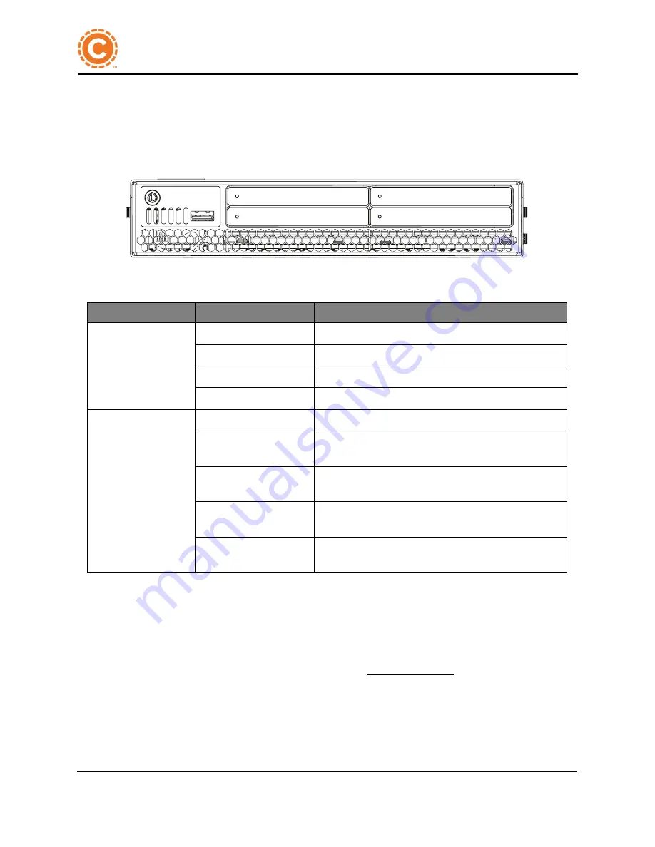
The power button is located on the front panel. The power button controls the power to the system's
main board and is green when powered on. An LED on each hard drive bezel indicates status and
activity. The front panel incorporates a USB port.
Figure 2 - 5: Front Panel
LED
Color
Description
Hard drive indicators
(Qty. 4, 1 Per hard
drive)
Green steady
Hard drive is quiesced.
Green flashing
Hard drive has activity.
Red steady
Hard drive has an error.
Red flashing
Hard drive is in RAID rebuild mode.
Power button indicator
Green steady
Appliance is powered on.
Blue steady
Power is connected and available to the system, but the
system is not powered on.
Yellow steady
The appliance is currently on and is requesting a grace-
ful shutdown from the Operating System.
Red steady
The appliance has experienced an error which should
be investigated.
Not illuminated
The appliance is not connected or power is not avail-
able.
Table 2 - 2. Front Panel LED Indicators
2.6 Rear Panel
The rear panel is where SAS, Ethernet, AC Power, USB, Serial Console, and HDMI connectors are
located. Holes in the panel allow air to flow out of the appliance . Ensure these areas are free from
cables, debris, or any kind of blockage. See Figure 2 - 6: -
Confidential
BT1 Security Appliance User Guide
2 System Overview BT1 Security Appliance


