Page of
17
31
HHR-4X66 Single-lane Kits - Using the Vend Button (continued)
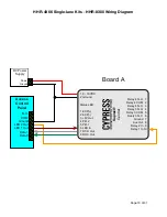
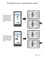
The diagram to the right
shows OUT Reader. The
Vend button is not being
pressed and the state of
Relay 3 on Board B is
normal (continuity between
Relay 3 Com and Relay 3
N.C.).
In this diagram, the Vend
button on the OUT Reader
is being pressed. The state
of Relay 3 on Board B is
active (continuity between
Relay 3 Com and Relay 3
N.O.).
1 8 - 16VDC
2 Ground
Status LED
1 EXP(+)
2 EXP(-)
3 +5V Out
4 P.R. 2
5 P.R. 1
6 LED In
7 D1/D Out
8 D0/C Out
Relay 4 N.O. 1
Relay 4 COM 2
Relay 4 N.C. 3
Relay 3 N.O. 4
Relay 3 COM 5
Realy 3 N.C. 6
Ground 7
Aux Out 8
Relay 2 In 9
Relay 1 In 10
Supr
ex®
Central
1 8 - 16VDC
2 Ground
Status LED
1 EXP(+)
2 EXP(-)
3 +5V Out
4 P.R. 2
5 P.R. 1
6 LED In
7 D1/D Out
8 D0/C Out
Relay 4 N.O. 1
Relay 4 COM 2
Relay 4 N.C. 3
Relay 3 N.O. 4
Relay 3 COM 5
Realy 3 N.C. 6
RS-232 TxD 7
RS-232 RxD 8
Ground 9
Aux Out 10
Relay 2 In 11
Relay 1 In 12
Supr
ex®
EXP Central
1 8 - 16VDC
2 Ground
Status LED
1 EXP(+)
2 EXP(-)
3 +5V Out
4 P.R. 2
5 P.R. 1
6 LED In
7 D1/D Out
8 D0/C Out
Relay 4 N.O. 1
Relay 4 COM 2
Relay 4 N.C. 3
Relay 3 N.O. 4
Relay 3 COM 5
Realy 3 N.C. 6
Ground 7
Aux Out 8
Relay 2 In 9
Relay 1 In 10
Supr
ex®
Central
1 8 - 16VDC
2 Ground
Status LED
1 EXP(+)
2 EXP(-)
3 +5V Out
4 P.R. 2
5 P.R. 1
6 LED In
7 D1/D Out
8 D0/C Out
Relay 4 N.O. 1
Relay 4 COM 2
Relay 4 N.C. 3
Relay 3 N.O. 4
Relay 3 COM 5
Realy 3 N.C. 6
RS-232 TxD 7
RS-232 RxD 8
Ground 9
Aux Out 10
Relay 2 In 11
Relay 1 In 12
Supr
ex®
EXP Central
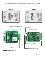
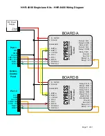
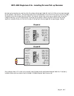
Board A
Board A
Board B
Board B

