Page of
31
31
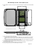
1 8 - 16VDC
2 Ground
Status LED
1 EXP(+)
2 EXP(-)
3 +5V Out
4 P.R. 2
5 P.R. 1
6 LED In
7 D1/D Out
8 D0/C Out
Relay 4 N.O. 1
Relay 4 COM 2
Relay 4 N.C. 3
Relay 3 N.O. 4
Relay 3 COM 5
Realy 3 N.C. 6
RS-232 TxD 7
RS-232 RxD 8
Ground 9
Aux Out 10
Relay 2 In 11
Relay 1 In 12
Supr
ex®
EXP Central
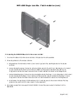
1 8 - 16VDC
2 Ground
Status LED
1 EXP(+)
2 EXP(-)
3 +5V Out
4 P.R. 2
5 P.R. 1
6 LED In
7 D1/D Out
8 D0/C Out
Relay 4 N.O. 1
Relay 4 COM 2
Relay 4 N.C. 3
Relay 3 N.O. 4
Relay 3 COM 5
Realy 3 N.C. 6
Ground 7
Aux Out 8
Relay 2 In 9
Relay 1 In 10
Supr
ex®
Central
HHR-4X66 Single-lane Kits - Installing External Pull-up Resistors
External pull-up resistors are used to pull up the voltage of damaged digital I/O pins to 5V, if the pin has been damaged
and is between 1.0V and 4.4V. Through-hole resistors with values between 1k and 2.7k Ohms can be used. The higher
the resistor value, the stronger the pull-up e
ff
ect. For instance, using a lower value pull-up resistor may not pull the
voltage all the way up to 5V. In these cases, a stronger pull-up resistor needs to be used. One end of the pull-up
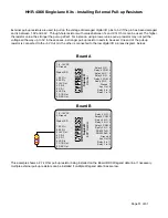
resistor is connected to the +5V Out pin; the other is connected to the low digital I/O pin
(see diagram, below).
Board A
Board B
This example shows a 2.7k Ohm pull-up resistor being installed on the Board B D0 Wiegand data line. If necessary,
multiple external pull-up resistors can be installed if multiple Wiegand data lines are low.

