PSoC Analog Coprocessor Pioneer Kit Guide, Doc. # 002-11190 Rev. *B
41
A.2.3
Protection Circuits
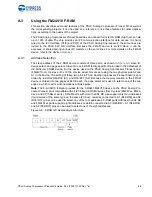
A positive temperature coefficient (PTC) resettable fuse is connected to protect the computer's USB
ports from shorts and over current (> 500 mA). ORing diodes are provided to prevent damage to
components when the board is powered from different voltage sources at the same time. ESD pro-
tection is provided on the USB connector.
Figure A-3. Power Supply Block Diagram with Protection Circuits
A.2.4
Current Measurement Jumper
The kit has an onboard facility to monitor both analog and digital power consumed by the PSoC
Analog Coprocessor. To measure the PSoC Analog Coprocessor power consumption, the jumper
J14 is populated in series with the power supplies (Analog/Digital) to the PSoC Analog Coprocessor
and can be used to measure current using an ammeter without the need to remove any components
from the board. The switch SW5 is provided to select between Analog/Digital power domain. The
KitProg2 on the board is also able to measure the power consumption of the PSoC Analog
Coprocessor using its internal Del-Sig ADC and SAR ADC. For this purpose, either a 1 Ohm shunt
resistor or 10 Ohm shunt resistor can be selected using the jumper J14. Connect an ammeter
between terminals 3 and 4 of the jumper J14 to measure the PSoC Analog Coprocessor current
consumption manually.
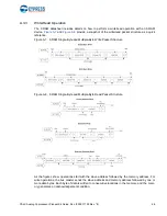
shows the detailed circuit for analog/digital power monitoring.
Figure A-4. Detailed Circuit of Current Measurement Switch
I/O
Header
US
B
PSoC
Analog
Coprocessor
5V
VIN
1.8V/3.3V/
5.0V
PSoC 5LP
VBUS
PTC
ESD
Protection
10 Pin Prog.
Header
Current
Measurement
Switch
(Analog/Digital)
and
Jumper
VBAT
VDD
Selection
Switch
Regulator
VDDA
Programmatic
Control
VBUS
5V
3.3V
VDDD
VDD
Power Monitoring
Jumper Settings
1 & 3 -> 10 Ohm Shunt
2 & 4 -> 1 Ohm Shunt
3 & 4 -> Short out shunts
NO LOAD
NO LOAD
VSSD
NO LOAD
NO LOAD
POS1 -- Digital Power Montr.
POS2 -- Analog Power Montr.
To avoid leakage during low
power measurement and battery
operation remove R67
NO LOAD
NO LOAD
NO LOAD
P4_VDD
P4_VDDD
P4_VDDA
VTARG
P5LP3_1
P5LP0_5
P5LP3_7
P5LP0_6
R71
10 Ohm
TP23
RED
TP11
RED
R173
ZERO
R74
ZERO
TP14
BLACK
R75
1 Ohm
R67
ZERO
TP24
RED
R76
ZERO
POS1
POS1
POS2
POS2
SW5
DPDT
1
2
3
4
5
6
R72
ZERO
J14
CON2x2
1
2
3
4
L5
330 OHM @ 100MHz
L4
330 OHM @ 100MHz


