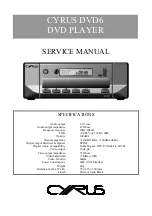
background image

SERVICE MANUAL

SPECIFICATIONS

Audio output

2.1V rms

                           Audio output impedance

47 Ohms

Frequency response

20Hz-20kHz

THD

<0.002% (ref. 1kHz, 0dB)

S/n ratio

100dBA

Channel separation

>110dB (1kHz), >100dB (20kHz)

Digital output Electrical & Optical

SPDIF

Digital Audio Compatibility

Dolby Digital, DTS, PCM 44.1k, 24/96k

Video output

1Vpk-pk

Video output impedance

75 Ohms

Video bandwidth

>5MHz (±3dB)

Video S/n ratio

60dB

Power Consumption

20W (10W Standby)

Weight

3Kg

Dimensions (H x W x D)

78 x 215 x 360 (mm

Finish

Silver or Satin Black

CYRUS DVD6

DVD PLAYER

Summary of Contents for DVD6

Page 1: ...aration 110dB 1kHz 100dB 20kHz Digital output Electrical Optical SPDIF Digital Audio Compatibility Dolby Digital DTS PCM 44 1k 24 96k Video output 1Vpk pk Video output impedance 75 Ohms Video bandwidth 5MHz 3dB Video S n ratio 60dB Power Consumption 20W 10W Standby Weight 3Kg Dimensions H x W x D 78 x 215 x 360 mm Finish Silver or Satin Black CYRUS DVD6 DVD PLAYER ...

Page 2: ......

Page 3: ...are displayed prominently on the Cyrus DVD6 base cover label They indicate that the following cautions must be observed by all personnel CAUTION TO REDUCE THE RISK OF ELECTRICAL SHOCK DO NOT REMOVE COVER OR BACK THERE ARE NO USER SERVICEABLE PARTS INSIDE THE PRODUCT ALWAYS REFER SERVICING TO QUALIFIED SERVICE PERSONNEL ...

Page 4: ...vice Manual Issue 1 2 The notice below shows the position of caution labels which alert the service technician to the presence of a laser device CLASS 1 CLASS 1 LASER PRODUCT LASER PRODUCT CAUTION VISIBLE AND INVISIBLE LASER RADIATION WHEN OPEN AVOID DIRECT EXPOSURE TO BEAM ...

Page 5: ...ent replacement Block diagrams Technical description Fault finding Alignment Control software Use with a PSX R The MC Bus system Chassis parts drawing Chassis parts list Front panel parts drawing Front panel parts list PCB parts lists Schematic diagrams and PCB legends Changes from previous issue Appendix 1 PCB artwork plots Appendix 2 ...

Page 6: ...ower fuse must both be replaced with original parts from Cyrus to be the correct type for the new zone AC fuse There are no user replaceable fuses fitted to the DVD6 Power consumption The maximum power consumption figure is indicated Serial number Each DVD6 carries a serial number code which identifies the following Type of product Market destination Build number The serial number is visible throu...

Page 7: ...damaged before fitting Measuring circuits with SMD capacitors and resistors Avoid using sharp pointed probes directly on the component end caps Measure voltages from the PCB pad next to the component Static precautions SMD components particularly ICs may be damaged by the static levels present in the workshop Damage caused by static may not immediately cause component failure but could cause parti...

Page 8: ...dering iron 1 Apply a little flux to the connections 2 Place the component in position 3 Tin the soldering iron bring the tip into contact with the PCB pad and flow solder to the joint Avoid bringing the soldering iron tip directly into contact with the component Removing SMD ICs from the PCB 1 Using fine tipped side cutters or tweezer cutters snip all the leads of the device and remove the IC bod...

Page 9: ...ESP part no HPD10 or HPD30 soldering iron RS part no 307 9598 magnifier RS part no 614 312 desoldering braid RS part no 229 3866 Contacts Electronic Tools Supplies Electronic Component Supplies Intertronics Ltd Unit 9 Station Field Industrial Estate Banbury Road Kidlington Oxfordshire OX5 1JD 44 0 1865 842842 44 0 1865 842172 fax email info intertronics co uk http www intertronics co uk RS Compone...

Page 10: ...r PCB IC403 Digital Out Main PCB Laser Mechanism Control PCB Keyswitches Serial Data DISPLAY DRIVER IC101 IC403 DAC IC301 Comp Out BUFFER IC701 702 S Video R G B Y C Video Amp T302 T304 Video Amp T301 T303 Video Amp T203 T208 Video Amp T202 T207 Video Amp T201 T205 No Disc T204 T209 T206 IC404 COMP DAC LP FILTER ...

Page 11: ...c D503 VR501 VR507 VR512 5V HV2 HV2 HV1 HV1 LV2 LV2 LV1 LV1 VR502 5V Video 12Van 12Van 5V Video 8V Standby T512 Switch 3V3 LCD Backlight VR509 T501 T401 T407 Video Amp Video Amp Video Amp Video Amp Video Amp Video Amp DAC Laser Mechanism Main PCB D502 D501 VR505 5V Vcc 5V 5V 3V3 12V VR506 VR511 Digital Supply T507 T508 D504 D505 Micro ...

Page 12: ...ontrol system System control for the player is provided by IC403 This IC accepts commands from the IR handset front panel keys or MC Bus from another unit and translates them into instructions for the mechanism The communication interface to the mechanism is via a parallel bus to IC404 then to the mechanism via a serial bus Status information is returned back through this IC from the mechanism IC4...

Page 13: ...y The Zener diodes connected across the video output signals are included to protect against the high potentials that can sometimes be transferred to the DVD6 signal circuitry when hot wired to a TV which has not been powered down SCART output The SCART output socket is a single 21pin connection carrying audio video and control signals to a TV monitor through a single cable SCART video signals inc...

Page 14: ...cific instructions to restore the correct region setting Power supplies Power is supplied from a 37VA toroidal power transformer bolted to the back plate The secondary has a low voltage winding 7Vac and split rail high voltage windings 11Vac Secondary outputs are connected to the PCB via a polarised connector These supplies are sub regulated into 6 areas as described in the following sections Moto...

Page 15: ...pply is derived from a full bridge rectifier D502 smoothed by C501 Due to the current demands on this supply two regulators are used VR505 6 Both are mounted to a heatsink to improve power dissipation A 5V digital supply is driven by a fixed voltage low dropout 2940 5 0 regulator VR505 This provides a supply for the microprocessor section and all associated control circuitry Video power supply Pow...

Page 16: ...details of the MC Bus system see the MC Bus section in this Service Manual Laser module Work to the laser mechanism requires precision and in many cases specialist equipment Contact Cyrus UK for advice in the case of a defective laser module Removing the laser mechanism Eject the disc drawer and disconnect the power Turn the player upside down and remove front drawer trim by applying gentle pressu...

Page 17: ...nual Issue 1 13 RGB traces can be taken off the test points as below Red TP202 Green TP203 Blue TP204 When one of the primary colour components is missing the result is the colour inverse of the missing component Missing colour Resulting colour Red Cyan Green Magenta Blue Yellow ...

Page 18: ...CYRUS DVD6 ALIGNMENT Cyrus Electronics Ltd Dec 2003 Cyrus DVD6 Service Manual Issue 1 14 Alignment There is no video or audio alignment required for the DVD 6 during service or maintenance ...

Page 19: ...n if the software has been changed electrically A reliable method to check the installed software version without dismantling the player is to read it from the display of as follows 1 Connect power to the unit and set to Standby power light red 2 Press and hold the Eject key 3 The software version and release date will be shown on the display If it becomes necessary to install a later version of s...

Page 20: ...3 The signals are buffered into and out of this IC as shown in the diagram The resistor bias at the MC Bus input ensures that the line idles high 5V if no MC Bus connection is made to another product MC Bus system tests The MC Bus system can be tested by connecting the DVD6 into a known working Cyrus system Note that MC Bus must be connected as a closed loop as shown in the diagram below It is als...

Page 21: ...CYRUS DVD7 CHASSIS PARTS DRAWING Cyrus Electronics Ltd Dec 2003 Cyrus DVD6 Service Manual Issue 1 17 a d e b c q r s f g h i p ...

Page 22: ...ly 2 AM MTERM AC power inlet 3 AM M8BOL 55 Transformer bolt 4 DV TX230 Transformer 5 DV CB06W 70 Flexfoil 6 way 6 DV CB16W 75 Flexfoil 22 way 7 DV CB22W 75 Flexfoil 16 way 8 MPEG board 9 DV MASD1 DVD mechanism 10 See following pages Front panel complete 11 DV COVER B DV COVER S Chassis black Chassis silver 12 DV CRLOC Mechanism mounting clamp 13 AM HCLMP Heatsink clamp ...

Page 23: ...CYRUS DVD7 FRONT PANEL PARTS DRAWING Cyrus Electronics Ltd Dec 2003 Cyrus DVD6 Service Manual Issue 1 19 017 DVD7 a d b c ef g h i ...

Page 24: ...w 5 D3 FRONT B D3 FRONT S Technical moulding black Technical moulding silver 6 DV FACIA B DV FACIA S Front fascia black Front fascia silver 7 DV DRWFR B DV DRWFR S Drawer front black Drawer front silver 8 AM BPPPLT B Base plate 9 AM BFOOT Rubber foot Packing list Part Number Description AM MLEUR Mains lead Europe AM MLUKM Mains lead UK DV REMCL Remote control AM REMCL BAT Remote control battery D3...

Page 25: ...NOTES Cyrus Electronics Ltd Dec 2003 Cyrus DVD6 Service Manual Issue 1 21 ...

Reviews: