4.5.1
UV Flow Cell 2 mm and UV Flow Cell 10 mm
Installing the flow cell
Follow the steps below to install UV Flow Cell 2 mm and UV Flow Cell 10 mm.
NOTICE
To avoid damaging the optical fibers, press only on the cell body,
never on the optical fibers.
Step
Action
1
Unpack the flow cell. Do not remove the red protective caps from the inlet or
outlet, or the black protective caps on the optical fiber connectors.
2
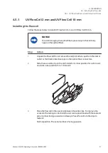
Slide the rear white clip on the cell holder to its inner position for a 2 mm cell
and to its outer position for a 10 mm cell.
3
Place the flow cell in the opening between the white clips. To improve the
access to the tubing connections the cell can be positioned with the text and
serial number facing upwards or sideways. Press the cell into the clips to
fasten it.
Normal position. The serial number is facing upwards.
4 Installation
4.5 Installing the flow cells
4.5.1 UV Flow Cell 2 mm and UV Flow Cell 10 mm
Monitor UVis-920 Operating Instructions 29055049 AF
31
Summary of Contents for Monitor UVis-920
Page 2: ...Pageintentionallyleftblank ...
Page 93: ...Pageintentionallyleftblank ...


