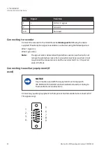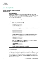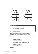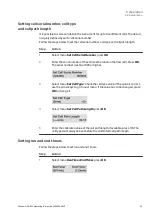
Pin
Signal
Function
1
+
0 V to 1 V signal
2
-
Ground
3-6
Not used
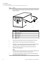
Connecting to recorder
Connect the recorder to the miniDIN-socket
Analog out 0-1 V using the cable
supplied. The absorption signal is available on a channel using the following wires:
Wire 1: signal (+)
Wire 2: ground (-)
Note:
The signal cable is delivered with protective covers on each wire. Do not
remove the protective covers from unused connections as a short circuit
may disturb the measurements. Set the recorder to 0 V to 1 V input, full
scale, 0 V offset.
Connecting to auxiliary equipment (if
used)
NOTICE
Any computer used with the equipment must comply with
IEC
60950 or IEC
62368-1 and be installed and used according to
the manufacturer's instructions.
Connect any auxiliary equipment to the 9-pole D–Sub female Remote connector (5 V
TTL signals only).
1
4
2
3
5
6
9
7
8
4 Installation
4.6 Electrical connections
40
Monitor UVis-920 Operating Instructions 29055049 AF
Summary of Contents for Monitor UVis-920
Page 2: ...Pageintentionallyleftblank ...
Page 93: ...Pageintentionallyleftblank ...

