CR-MM-1-0-00
PS-28 Cruiser
PS-28N Cruiser
CHAPTER 10 – POWERPLANT
Date of issue: 2015-09-23
Revision No.: 15
10 - 5
10.2.1.2 Engine cowling
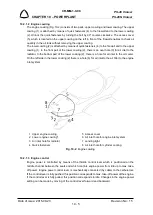
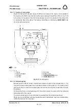
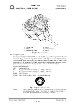
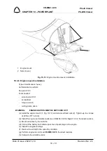
The engine cowling (Fig. 10-2) consists of two parts: upper cowling and lower cowling. The upper
cowling (1) is attached by means of quick fasteners (4) to the firewall and to the lower cowling
(2). Unlock the quick fasteners by turning the bolt by 90° counter-clockwise. The access cover
(5), which is located on the upper cowling on the left in front of the firewall enables to check oil
quantity in the oil tank without removing the upper cowling.
The lower cowling (2) is attached by means of quick fasteners (4) to the firewall and to the upper
cowling (1). In the front part of the lower cowling (2), there is an oval hole (3) for air inlet to the
radiator. In the bottom part of the lower cowling (2), there is a hole for air inlet to the oil cooler.
On the left side in the lower cowling (2) there is a hole (6) for air inlet to the air filter to the engine
inlet system.
1 Upper engine cowling
5 Access cover
2 Lower engine cowling*
6 Air inlet hole for engine inlet system
3 Air inlet hole for radiator
7 Landing light
4 Quick fasteners
8 Air inlet hole for cylinder cooling
Fig. 10-2
: Engine cowling
10.2.1.3 Engine control
Engine power is controlled by means of the throttle control lever which is positioned on the
middle channel between the seats and which controls engine power from idle up to max. take-
off power. Engine power control lever is mechanically connected (by cable) to the carburetors.
If the control lever is fully pushed, this position corresponds to max. take-off power of the engine.
If the control lever is fully pulled, this position corresponds to idle. Changes in the engine power
setting can be made by moving of the control lever forward and backward.

