PS-28 Cruiser
PS-28N Cruiser
CR-MM-1-0-00
CHAPTER 10 – POWERPLANT
Revision No.: 20
Date of issue: 2017-12-05
10 - 42
10.4.2.3 Klassic 170/3/R propeller blades pitch setting
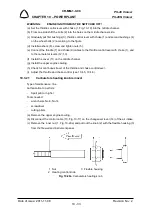
(a) Pull out each blade to it´s outer limit-away from the hub as there is an 1.5 mm (1/16
″
)
movement range in its lock for expansion.
(b) Use protractor to blades pitch adjustment (digital with an alternative zero or ordinary bubble
type). Place protractor 50 mm (2 in) from the tip of each blade. You can also use wedges
and set the pitch on a flat level table before mounting the propeller on engine.
(c) Set blades pitch to 17.5
°
±
0.5
°
.
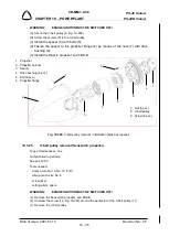
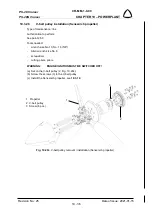
(d) Tighten the bolts in this sequence: first tighten the bolts M6 on spokes of the hub by moment
10 Nm (7.4 ft.lb.) then tighten the fixing bolts M8 by moment 22 Nm (16.2 ft.lb.) (see Fig. 10-
21).
(e) Secure fixing bolt heads by lock wire (see 15.8.2).
10.4.3 INTENTIONALLY LEFT 10.EMPTY
10.4.4 3B0R5R68C propeller inspections
10.4.4.1 Summary of propeller periodical inspection
•
Annual inspection of the propeller.
•
Major periodic inspection on 2,000 hours of operation.
NOTE:
Inspections are described in the propeller manufacturer documentation -
Sensenich Three Blade Composite Aircraft Propeller - Installation and
Operation Instructions for Rotax Engines, Instructions for Continued
Airworthiness.
10.4.5 Adjusting throttle control
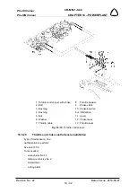
(a) Pull the throttle control to the stop. The throttle lever on the carburetor (5, Fig. 10-9) must be
on the stop. The bowden must be supported in the terminals.
(b) Release the nut on the control lever (5) and take up any slack on the cable and tighten up
the nut.
CAUTION:
CONTROL CABLE SHOULD NOT BE TOO TIGHT FOR THE REASON OF A
POSSIBLE DEFORMATION OF THE CONTROL LEVER ON THE
CARBURETOR.
(c) Check again whether the controller and the lever on the carburetor are on the stops. If not,
perform adjusting by means of adjustable terminals on bowdens.
(d) In order to prevent the bowdens at the carburetor from shifting out from the terminals, secure
the bowdens with lock wire. Mark all bolted joints with red paint.
10.4.6 Adjusting choke control
(a) Set the choke lever to the stops position and put it back about 3 mm (
1/8 in
). The lever of
choke control on the carburetor (6, Fig. 10-9) must be on the stop. The bowden must rest
on the terminals.
(b) Release the bolt on the lever of choke control (6), slightly loosen the cable and tighten up
the bolt.

