CR-MM-1-0-00
PS-28 Cruiser
PS-28N Cruiser
CHAPTER 12 – INSTRUMENTS AND AVIONICS
Date of issue: 2021-01-15
Revision No.: 25
12 - 21
Antennas
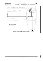
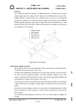
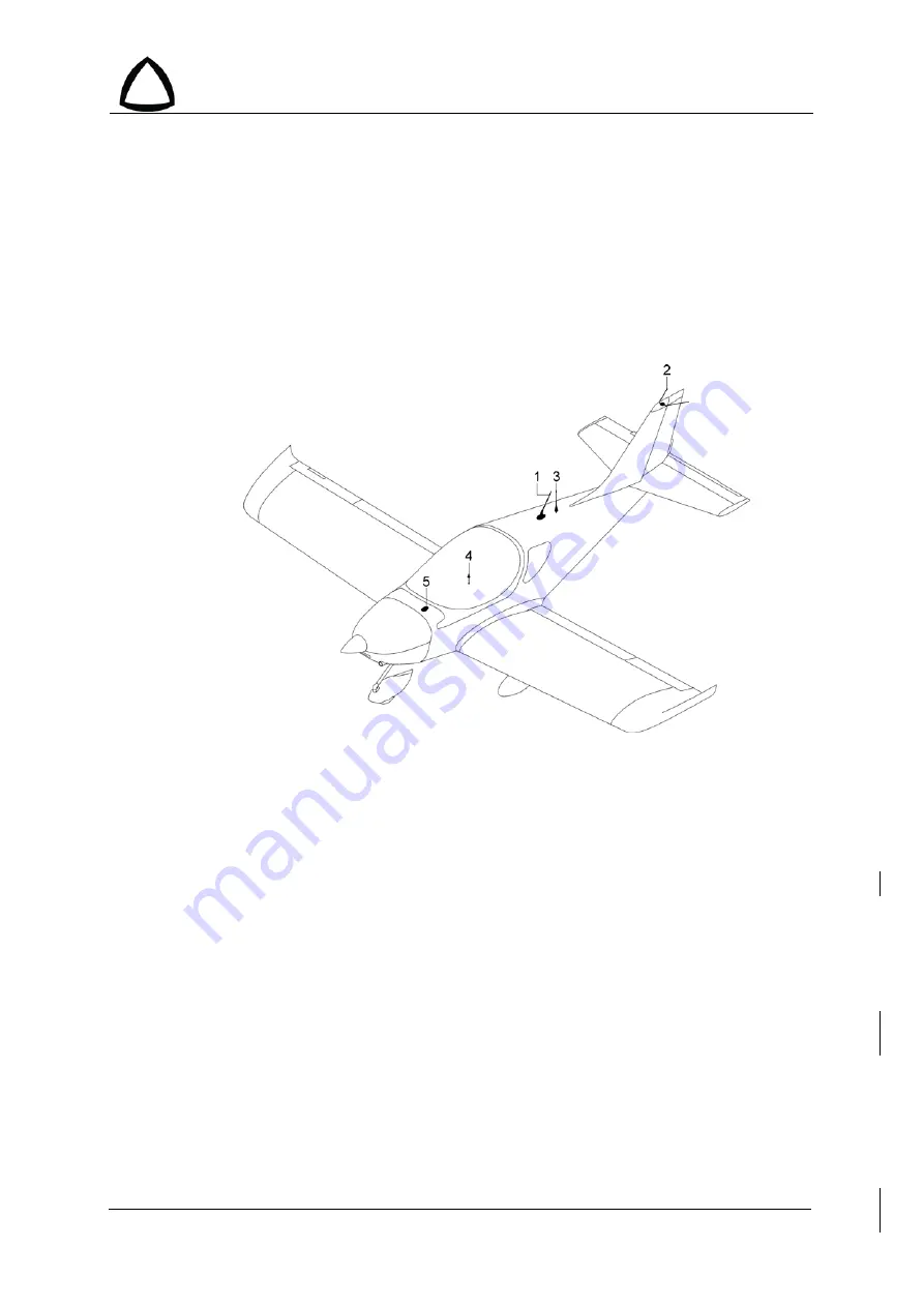
Fig. 12-22 shows the antenna locations. The COMM antenna (1) is installed on the upper part
of the fuselage behind the canopy. The ELT antenna (3) is installed directly in the rear of the
COMM antenna. The NAV antenna (2) is installed on the top of the fin. The transponder
antenna (4) is installed on the bottom part of the fuselage. The GPS antenna (for GPSMAP
695/696 and GPS Aera 510) is attached to the upper side of the instrument panel cover; GPS
antenna (5) for GTN 750 GPS / NAV / COM or Skyview System is installed on the upper part
of the fuselage in front of canopy.
Fig. 12-22
: Antenna locations
12.2.6 Dynon SkyView system
Dynon SkyView system is the next generation of glass panel avionics for light sport aircraft.
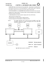
The system architecture is shown on Fig. 12-23.
The SV-D1000 and SV-HDX1100 displays are very bright, high-resolution screens and contain
the main control CPU, graphics processor, and terrain data-base. Displays can act as a
Primary Flight Display (PFD) with Synthetic Vision, an Engine Monitoring System (EMS), and
a Moving Map in a variety of customizable screen layouts.
The most used functions are accessed via two rotary/multi-direction joysticks. Almost all other
in flight commands are all available via eight buttons. SV-HDX1100 also have touchscreen
display.
Every SkyView system display and module is connected by two independent power and data
buses. The failure of any bus connection or module results in automatic fail-over to a working
bus or module.
Two SV-BAT-320 Backup Batteries provides over an hour of backup power to displays and
modules.
1 COMM antenna
2 NAV antenna
3 ELT antenna
4 XPDR antenna
5 GPS antenna


