PS-28 Cruiser
PS-28N Cruiser
CR-MM-1-0-00
CHAPTER 12 – INSTRUMENTS AND AVIONICS
Revision No.: 15
Date of issue: 2015-09-23
12 - 14
12.2.4 Engine instruments
Engine parameters (RPM, CHT or CT***, EGT, oil pressure and temperature, fuel pressure,
manifold pressure) are displayed either on the EMS D120, on the classical analog instruments
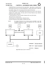
or on the SkyView screens. A typical example of the EMS display is shown in the Figure 10-
3. The EMS D120 is located on the right side of instrument panel. The engine parameters
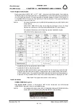
color marking is shown in Tab.12-2.
NOTE:
For detail information refer to EMS D120 Installation Guide (P/N 100591-000,
latest edition).
EFIS D100 / EMS D120 setup and setting the privileges of user for these
devices are mentioned in the Service Bulletin SB-SC-013, latest edition.
For detailed information refer to SkyView System Installation Guide
(P/N 101320-016, Revision Q or later).
Value
Minimum
Limit
(red line)
Caution
Range
(yellow arc)
Normal
Operating
Range
(green arc)
Caution
Range
(yellow arc)
Maximum
Range
(red line)
Engine speed
[RPM]
-
0 – 1,400
1,400 – 5,500
5,500 – 5,800
5,800
Oil
Pressure
0.8 bar
0.8 – 2 bar
2 – 5 bar
5 – 7 bar
7 bar
Oil
Temperature
50 °C
50 – 90 °C
90 – 110 °C
110 – 130 °C
130 °C
Cylinder head
Temperature (CHT)
-
to 50 °C
50 – 135 °C
-
135 °C
Coolant Temperature
(CT)***
-
-
50 – 120 °C
-
120 °C
Exhaust
Gas Temp.
-
to 300 °C
300 – 850 °C
850 – 880 °C
880 °C
Fuel
Pressure
0.15 bar
-
0.15 – 0.4 bar
0.15 – 0.5 bar*
-
0.4 bar
0.5 bar*
0.14 bar**
0.14 - 0.15 bar** 0.15 - 0.50 bar** 0.50 - 0.51 bar**
0.51 bar**
Manifold pressure
-
-
10 – 35 in Hg
* Applicable only for fuel pump from S/N 11.0036.
** Applicable for Dynon SkyView system.
*** Applicable for ROTAX 912 ULS2 engines from S/N 6 781 410 inclusive and for 912 S2
engines from S/N 4 924 544 inclusive, equipped with new cylinder heads, P/N 413185
for 2/3 cylinder head. The coolant temperature instead of cylinder head temperature is
measured. On Dynon EMS D120 screen the coolant temperature is displayed as “CHT”.
Tab. 12-2:
The engine instruments colour marking
12.2.5 Avionics
COMM, COMM/NAV system
The Apollo SL-30
includes a 760-channel VHF Comm transceiver and 200-channel
VOR/LOC/GS navigation receiver with DME display.
NOTE:
For detailed information refer to SL-30 Installation Manual (P/N 560-0404-03a,
latest edition) and Pilot
′
s Guide (P/N 560-0403-01, latest edition).
Fig. 12-9
: SL-30 COMM/NAV

