CR-MM-1-0-00
PS-28 Cruiser
PS-28N Cruiser
CHAPTER 12 – INSTRUMENTS AND AVIONICS
Date of issue: 2018-09-27
Revision No.: 22
12 - 31
12.3.10
Installation of the EFIS D100
Type of maintenance: line
Authorization to perform:
See point 2.5.3.
Tools needed:
-
7/64 Allen wrench
(a) Remove the protective covers from the rear ports on the unit.
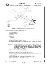
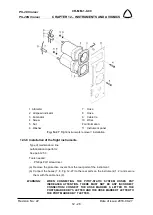
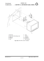
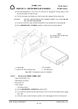
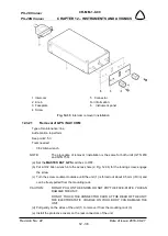
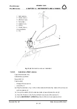
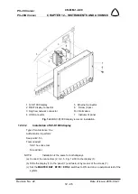
(b) Connect the hoses (5, 6, Fig. 12-28) to the rear ports (3, 4) on the unit (1) and secure them
with cable ties (7).
WARNING:
WHEN CONNECTING THE PITOT-STATIC SYSTEM HOSES PAY
INCREASED ATTENTION. THERE MUST NOT BE ANY INCORRECT
CONNECTION! CONNECT THE HOSE MARKED S LETTER TO THE
PORTS MARKED BY STATIC AND THE HOSE MARKED T LETTER TO
THE PORT MARKED BY PITOT.
NOTE:
The hose for static pressure line mark by
S
letter and for total pressure mark
by
T
letter.
(c) Connect the connector (4) to the unit.
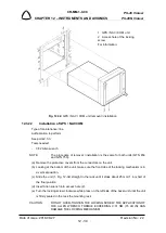
(d) Slide the unit (1) into the rack (9). Engage the locking screw so that the latch front lobe
touches the rack.
(e) Turn the locking screw clockwise so that the rear lobe engages the mounting rack.
CAUTION:
DO NOT OVER-TIGHTEN THE LOCKING SCREW. YOU CAN DAMAGE
THE LOCKING MECHANISM.
(f) Continue to turn the screw until the unit is fully installed in the mounting rack.
(g) Carry out check of pitot-static system tightness / Dynon avionics pitot / static test (see
12.4.1, 12.4.2).
(h) Set the
MASTER BAT
,
AVIONICS
switches to ON and
do an operational test of the
system.
12.3.11
Removal of EDC-10A remote compass module
Type of maintenance: line
Authorization to perform:
See point 2.5.3.
Tools needed:
-
screwdriver
CAUTION:
DO NOT USE STANDARD MOUNTING HARDWARE. ALL MOUNTING
HARDWARE IS MADE FROM BRASS – NON FERROUS MATERIAL.
(a) Set the
MASTER BAT
,
AVIONICS
switches to OFF.
(b) Remove the cover on the bottom of the fuselage rear part.
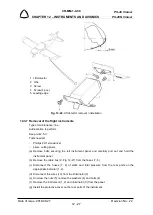
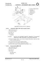
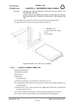
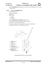
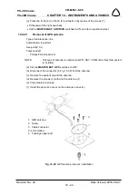
(c) Disconnect the connector (2, Fig. 12-29) from the compass module.
(d) Unscrew the screws (3) with the washers (4) and remove the compass module (1).

