CR-MM-1-0-00
PS-28 Cruiser
PS-28N Cruiser
CHAPTER 12 – INSTRUMENTS AND AVIONICS
Date of issue: 2018-09-27
Revision No.: 22
12 - 35
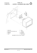
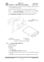
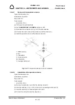
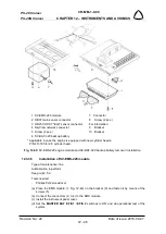
(a) Slide the transponder (1, Fig. 12-31) into the rack (3). Engage the locking screw so that
the latch front lobe touches the rack.
(b) Turn the locking screw clockwise so that the rear lobe engages the mounting rack.
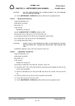
CAUTION:
DO NOT OVER-TIGHTEN THE LOCKING SCREW. YOU CAN DAMAGE
THE LOCKING MECHANISM.
(c) Continue to turn the screw until the transponder is fully installed in the mounting rack.
(d) Set the
MASTER BAT
,
AVIONICS
switches to ON and
do an operational test.
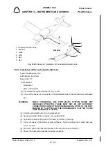
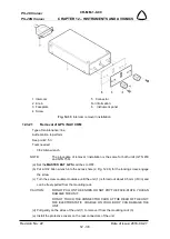
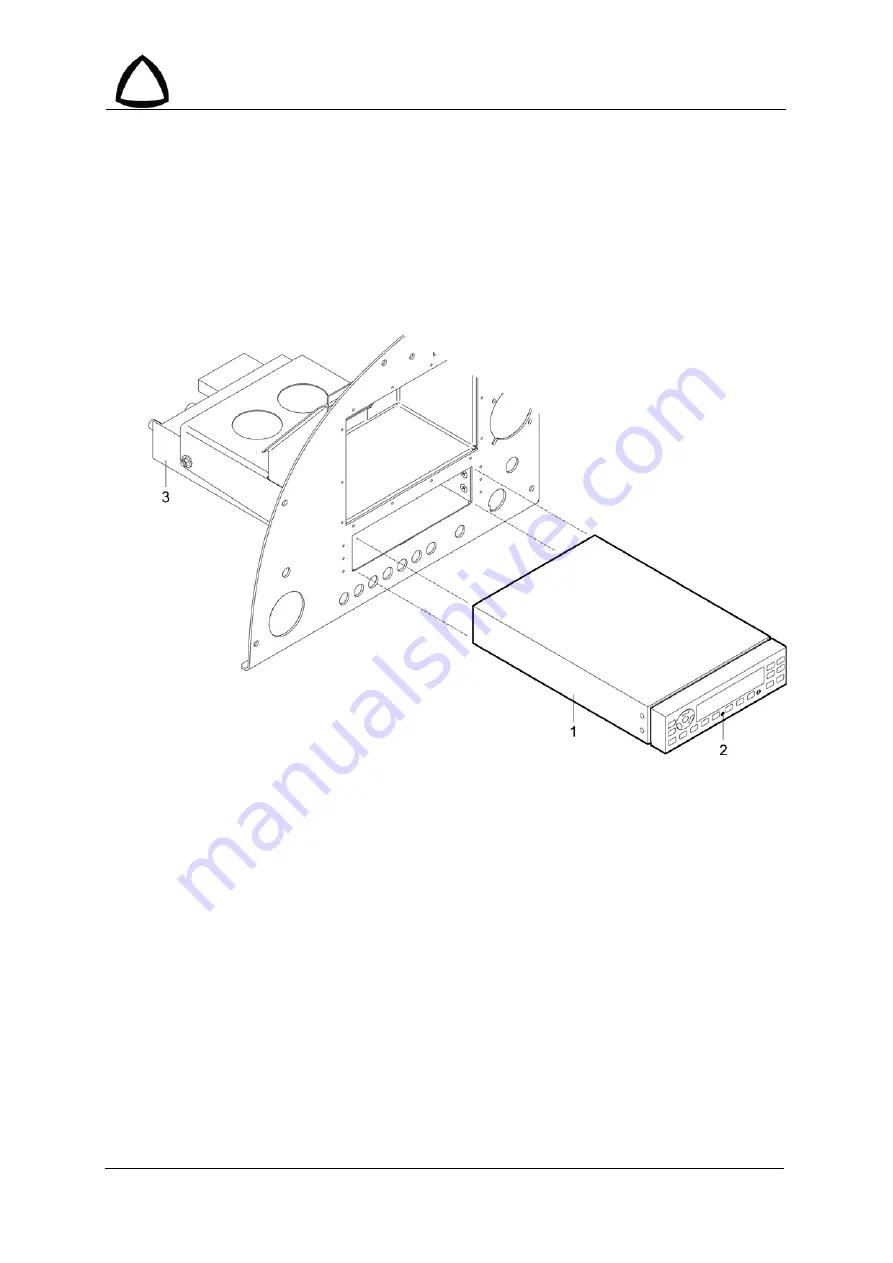
1 Transponder
For information:
2 Access hole of the locking screw
3
Mounting rack
Fig. 12-31
: Transponder removal / installation
12.3.17
Removal of COMM, COMM / NAV
Type of maintenance: line
Authorization to perform:
See point 2.5.3.
Tools needed:
-
3/32 Allen wrench
(a) Set the
MASTER BAT
,
AVIONICS
switches to OFF.
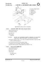
(b) Put a 3/32 Allen wrench into the access hole (2, Fig. 12-32) for the locking screw; engage
the screw.
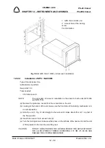
(c) Turn the screw counter-clockwise until the unit (1) disengages from the mounting rack.
NOTE
The location of the transponder
may be different.

