CR-MM-1-0-00
PS-28 Cruiser
PS-28N Cruiser
CHAPTER 12 – INSTRUMENTS AND AVIONICS
Date of issue: 2018-09-27
Revision No.: 22
12 - 39
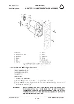
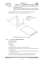
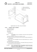
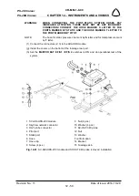
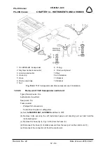
Fig. 12-34
: GPS / NAV / COM unit removal / installation
12.3.22
Installation of GPS / NAV COM
Type of maintenance: line
Authorization to perform:
See point 2.5.3.
Tools needed:
-
3/32 Allen wrench
NOTE:
The procedure of removal / installation is the same for both units (GTN 650
and GTN 750).
(a) Remove the protective covers from the connectors on the unit.
(b) Looking at the bottom of the unit, make sure the front lobe of the locking mechanism is in
a vertical positron.
(c) Slide the unit (1, Fig. 12-34) straight in the rack until it stops about 25 mm (1 in) short of
the final position.
(d) Insert Allen wrench into access hole (2).
(e) Turn the locking screw clockwise while press on the left side of the bezel unit until the unit
is firmly seated in the rack the mounting rack.
CAUTION:
DO NOT OVER-TIGHTEN THE LOCKING SCREW. THE APPLICATION OF
THE ALLEN WRENCH TORQUE EXCEEDING 0.01 NM (15 LB IN) CAN
DAMAGE THE LOCKING MECHANISM.
1 GPS / NAV / COM unit
2 Access hole of the locking
screw
For information:

