JF-1A Conductivity Sensor
A440-009
Page 36 of 56
FEBRUARY 2009
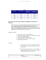
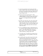
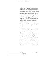
e) Read the current slope constant by sending the “FS” command (label as FS-
old).
f) Mathematically determine the new FS-new = C-old/C-std* FS-old.
g) Enter new calibration value using command “FS=FS-new”.
h) Check by returning to run mode using the ***R command.
i) Iterate steps a-h as is needed to gain a reading where the JF-1 sensor is less
than 10% different from the C-std value.
j) Save constant by returning to Open Mode and using the “***E” command.
k) Repeat the Zero Adjustment in 2.4 Above.
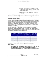
2.5 4-20 mA OUTPUT CALIBRATION
General:
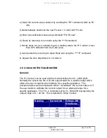
The JF-1 Sensor can be used with fuel conductivities from 0 – 2000 pS/M.
Normally the sensor has the 4-20 mA output scaled for a specific range which
allows the user to optimize the interface for a specific application. The
procedure below can be followed to either “re-calibrate” the current output or if
the user elects to calibrate the current output for an alternate range for a
specific application. The JF-1 is nominally set for 0 – 500 pS/M representing the
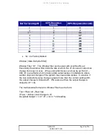
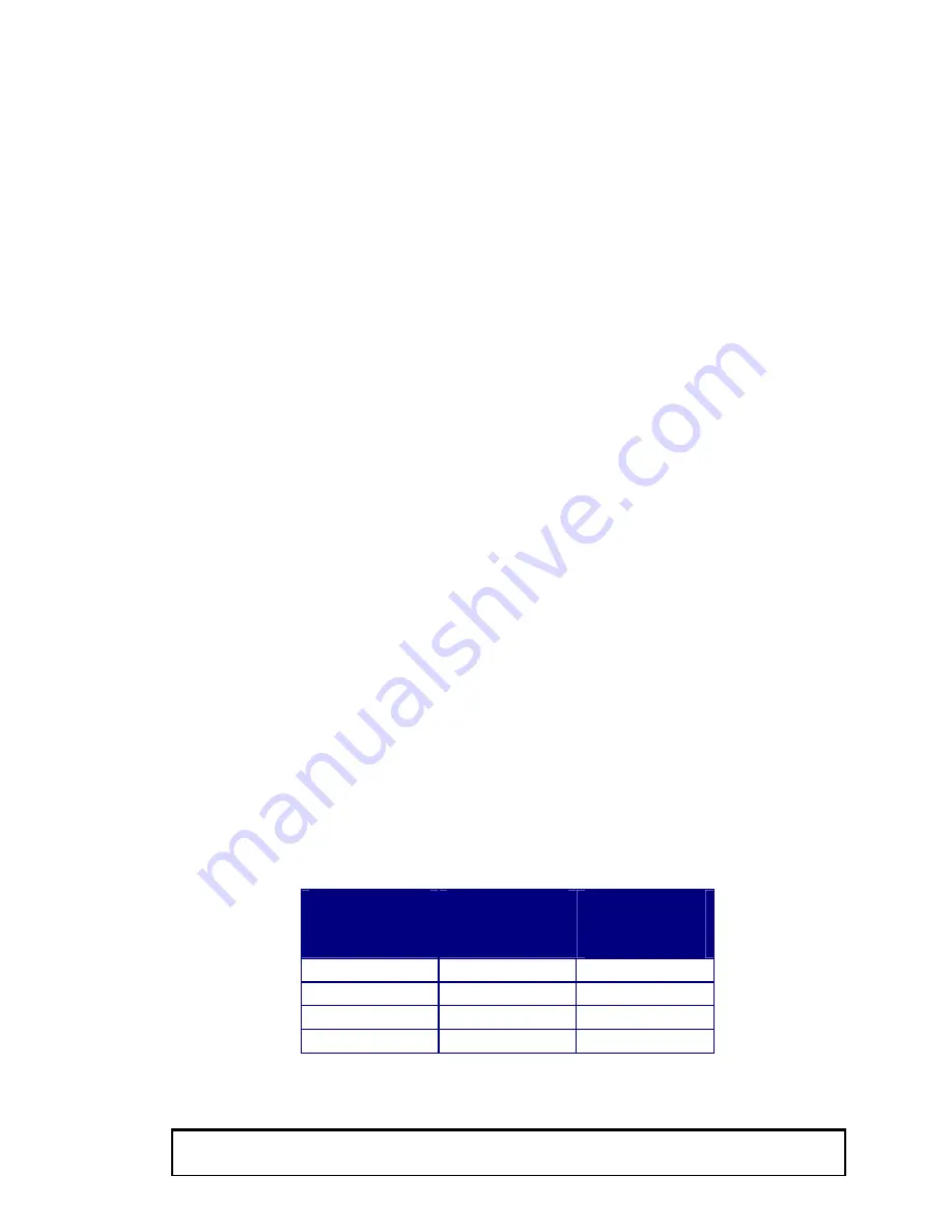
output range of 4 – 20 mA. This is detailed in Table 1 below:
Reading
Current mA
Voltage 250
Ohm Sense
0
4.0
1.00
125
8.0
1.25
250
12.0
2.50
375
16.0
3.75

