JF-1A Conductivity Sensor
A440-009
Page 45 of 56
FEBRUARY 2009
November 22, 2010
JF-1A FUEL CONDUCTIVITY SENSOR
Technical Application Note 10-007
Method of Adjustment Current Loop Output Settings
Background
In some applications of the JF-1A the user desires to change the range of either
the current or temperature output current loops. The standard settings are
Conductivity Loop 4 – 20 mA representing a Conductivity of 0 – 500 pS/M and
Temperature Loop 4 - 20 mA represents -20˚C to 60˚C.
(Note the output current adjustment/calibration is fully independent of the sensor
fluid calibration adjustment which will not be effected)
Warning: Prior to connecting serial ports or other equipment to the
JF-1A sensor carefully follow the instructions in: “Application Note 10-
006 Power/Ground Requirements for JF-1A, when 4-20 mA and Serial
Data Ports are used simultaneously” to avoid electrical damage to the
JF-1 Sensor.
Section 1.0 Method of Adjustment 4-20 mA output span JF-1 Sensor
:
Conductivity:
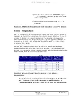
The JF-1 Sensor can be used with fuel conductivities from 0 – 2000 pS/M (Note JF-1A-
MA 0 – 200,000 pS/M). Normally the sensor has the 4-20 mA output scaled for a
specific range which allows the user to optimize the interface for a specific application.
The procedure below should be followed if the user elects to change the range for a
specific application. The JF-1 is nominally set for 0 – 500 pS/M representing the output
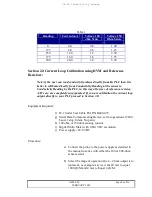
range of 4 – 20 mA. This is detailed in Table 1.

