JF-1A Conductivity Sensor
A440-009
Page 46 of 56
FEBRUARY 2009
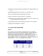
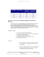
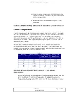
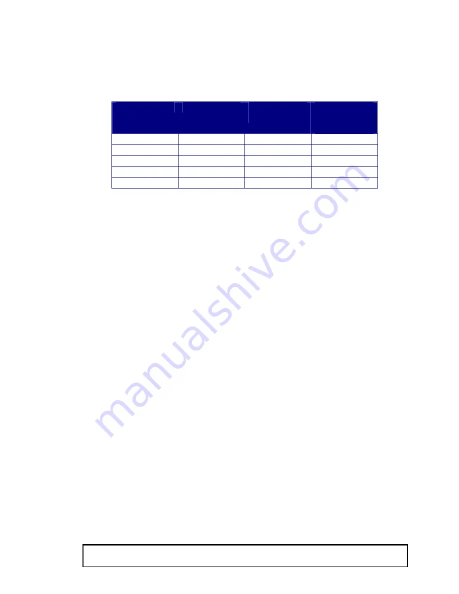
Table 1
Reading
Current mA
Voltage 100
ohm Sense
Voltage 250
Ohm Sense
0
4.0
0.4
1.00
125
8.0
0.8
1.25
250
12.0
1.2
2.50
375
16.0
1.6
3.75
500
20.0
2.0
5.00
Section 2.0 Current Loop Calibration using DVM and Reference
Resistors:
Note: if the user can read conductivity values directly from his PLC then it is
better to calibrate directly from Conductivity Reading at the sensor to
Conductivity Reading by the PLC, in this way all errors of reference resistor,
A/D’s etc. are completely incorporated. If you are calibration the current loop
output directly to your PLC proceed to Section 3.0.
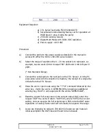
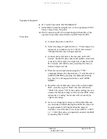
Equipment Required:
f)
JF-1 Serial Test Cable FSI P/N B440-079
g)
Serial Data Communicating Device, set for operation at 9600
baud, 1 stop, 8 data, No parity
h)
100 ohm or 250 ohm sensing resistor
i)
Digital Multi Meter with 0.001 VDC resolution.
j)
Power 24.0 VDC
Procedure:
a)
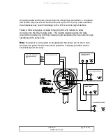
Connect the probe to the power supply as detailed in
the manual in series with either the 100 or 200-ohm
sense resistor.
b)
Select the range of operation the 4 – 20 ma output is to
represent, as example; say we want 20 mA to equal
1000 pS/M and 4 mA to Equal 0 pS/M.

