JF-1A Conductivity Sensor
A440-009
Page 50 of 56
FEBRUARY 2009
g)
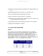
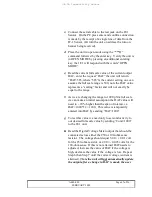
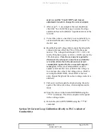
To test this value we need only to set conductivity to
our desired full-scale value by entering into the JF-1A
the value we want it to output in equivalent current.
This is done by entering “Cond=1000” to the JF-1 unit.
h)
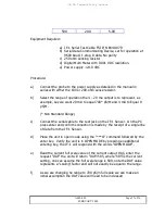
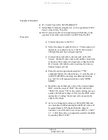
Read the PLC reading, this reading should equal 1000
pS/M. If this is not attained DAF needs to adjusted,
increase the value of DAF if the reading is low,
decrease the value if the voltage is high. After each
new entry of DAF you
MUST
reenter the
“Cond=1000” to change the sensor output after each
change in the DAF value. Repeat until the same
reading on the PLC is obtained as entered by the
COND command.
i)
After steps 5 – 6 are complete the user should now
check the “low end of the range to ensure the slope
adjustment has not resulted in “significant errors of the
low end.
j)
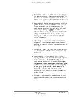
To test this value we need only to set conductivity to
our desired 4 mA value by sending “Cond=0” to the
JF-1A unit.
k)
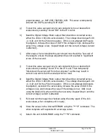
Again read the PLC output and verify a 0 pS/M
reading. If this is not attained DA0 needs to adjusted,
increase the value of DA0 if the Reading is low,
decrease the value DA0 if the reading is high
(note
you may need to disconnect the serial port due to the
additional current consumed in by some computer
serials ports if a Zero value cannot be attained).
Remember to reenter “COND=0” after each
adjustment of the DAO value is made to update the
sensor output.
l)
Full scale can then again be checked using the entry
again of the full-scale values, when complete unit is
ready.

