31
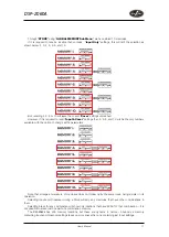
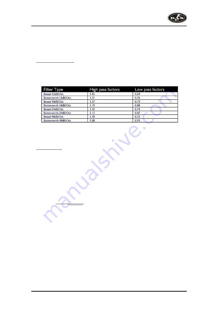
Crossover Filter Slopes
It should also be noted that the turnover frequency displayed on the screen is the -3dB point for all types
except Linkwitz-Riley where the -6dB point is shown. If the -6dB point is to be used for the Bessel or
Butterworth filter, take the required crossover frequency, multiply this by the appropriate factor from the
following table and then select the closest available frequency on the display.
Please note that unlike conventional analogue crossovers, crossover points and slopes are set with
absolute accuracy since component tolerance problems do not occur.
Please see page 12 for details of how to adjust the high and low pass crossover filter settings.
Time Alignment
A further advantage of the
DSP-2060A
over conventional products is the provision of an independently
adjustable delay section for each output. This allows the true arrival time from multiple drivers to precisely
aligned rather than relying on the compromise 'phase adjust' approach. Delay time is adjustable in 0.3uS
steps (0.1mm).
Please see page 12 for details of how to adjust the delay times.
To convert from units of time (i.e. milliseconds) to units of distance use the following formula:
1 millisecond = 343mm (1.126ft) @ 20Cº (68Fº)
To calculate time delay for a known distance, use:
Time delay = Distance (in metres)
20.06 x 273 + ºC
where ºC is the temperature in ºC.
To simplify this equation at 20Cº.
Delay (in mS) = 0.955 x Distancia (in feet)
(Distance in metres x 2.192) or (Distance in feet x 0.955)
Note: [ºC] = 0.5555 x ([ºF]-32)
√
DSP-2060A
User’s Manual
Summary of Contents for DSP-2060A
Page 2: ...DSP 2060A ...
Page 6: ...DSP 2060A User s Manual ...
Page 8: ...DSP 2060A User s Manual ...
Page 43: ......

