background image


27


231-914-0001-EN5 

10.4


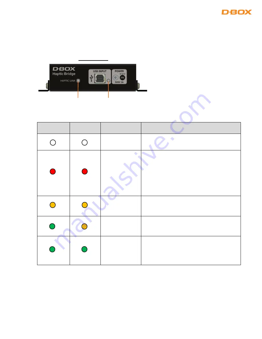
Troubleshooting with Haptic Bridge LEDs Status 

 
This section covers the status LED located on your Haptic Bridge: 


HAPTIC LINK 

LED 

USB LED 

STATUS 

SOLUTION 


Haptic Bridge is 
not powered. 

Make sure the power supply is properly 
connected. 


No USB 
connection is 
detected. 

Check that the USB cable is properly connected 
(both ends). Do not use a USB HUB. 
 
Make sure you are using the original USB cable 
provided with your controller. 
 
Make sure you have the latest version of Motion 
Core installed (see section 10.3). 


Unit is ready to 
operate but the 
platform is in 

Park

Make sure your platform is enabled. 


The platform is 
enabled but no 
motion is sent. 

USB LED should turn green as soon as you stream 
motion data to your haptic system. 


The device is 
operational and 
receiving motion 
data (or silence 
data). 


FRONT PANEL 

HAPTIC LINK 

LED


USB LED 

Summary of Contents for G5

Page 1: ...1 231 914 0001 EN5 231 914 0001 EN5 May 2022...

Page 2: ...ACKETS INSTALLATION 16 5 1 U Brackets Installation 16 5 1 L Brackets Installation 16 6 CONNECT YOUR HAPTIC SYSTEM 17 6 1 IEC Plug Lock Insert Installation Optional 17 6 2 4 Actuator Configuration 17 6...

Page 3: ...s 24 10 2 Reinitiate Your Haptic System 25 10 3 Update Software and Firmware 26 10 4 Troubleshooting with Haptic Bridge LEDs Status 27 10 5 Troubleshooting with D BOX System Monitor 29 10 6 Faults and...

Page 4: ...the elderly or those with other pre existing medical conditions All such persons should consult their physicians before using this D BOX Haptic System Use of this D BOX Haptic System is not recommende...

Page 5: ...bling and using your Haptic System Do not hesitate to contact us if you have questions Please make sure to provide the serial numbers Haptic Bridge Haptic Actuators of your Haptic System when contacti...

Page 6: ...6 231 914 0001 EN5 G5 HAPTIC SYSTEM SPECIFICATION...

Page 7: ...7 231 914 0001 EN5 G5 HAPTIC BRIDGE G5 HAPTIC ACTUATOR...

Page 8: ...single control box that is significantly smaller and sleeker than our previous design With voltage selection included in every individual actuator you can seamlessly go between 110V and 230V with the...

Page 9: ...he minimum spacing between actuators for adequate movement of the platform Measure the distance from a square surface enclosing all actuators see example below Respecting the spacing guidelines ensure...

Page 10: ...be level on the same flat surface for optimal operations Different levels could result in premature wear of the actuators 2 5 Weight Distribution Each actuator has a 250 lb maximal payload When integ...

Page 11: ...ACTUATOR ENDING INSTALLATION G5 haptic actuators come native with a non captive ending Captive endings are required when you want to bind the actuators to the floor or a sub frame 4 1 Non Captive Endi...

Page 12: ...models of spacer retainer All spacer retainers can be fitted on any model of ball joint 1 axis Allowing movement only on 1 axis X or Y 2 axes Allowing movement on 2 axes X and Y Here are some spacer r...

Page 13: ...from the spacer retainers as follow 4 haptic actuators Captive endings must be installed in the middle of the spacer retainers as follow INSTALLATION Never operate the haptic actuator without the endi...

Page 14: ...captive ending by removing the two 2 screws using a 4mm Allen Key STEP 2 Attach the piston adaptor with the four 4 provided screws Apply some blue thread locker on the screw threads then torque them t...

Page 15: ...en with a torque of 130 lbf in 15 Nm using a 5 8 16 mm wrench STEP 4 Install the ball joint assembly to the spacer retainer then attach it to the floor or sub frame with adequate hardware anchors bolt...

Page 16: ...Brackets Installation Install the U bracket first on your platform then attach the haptic actuators to the brackets using the provided screws NOTE Screws to attach the bracket to your platform are no...

Page 17: ...the appropriate diagram corresponding to your setup The Haptic Bridge must be connected directly into your computer USB port Using an external USB hub may create motion interruption and or system erro...

Page 18: ...18 231 914 0001 EN5 6 3 3 Actuator Configurations 6 4 2 Actuator Configurations OR OR...

Page 19: ...structions 8 SOFTWARE INSTALLATION There are two 2 D BOX software packages to be installed on your computer D BOX Motion Core and System Configurator section 8 2 Both are available at https www d box...

Page 20: ...el Motion Vibration Balance and latency There is also a test button to verify that your system is working properly Default Mode Park Haptic actuators will go to its lower position when there are no ha...

Page 21: ...aptic experiences for D BOX coded apps simulators games Use the adaptive gaming mode if your title is not in the list D BOX Coded Video Premium haptic experiences for D BOX coded movies TV shows using...

Page 22: ...y and activate your Adaptive Gaming profiles You can also share your favorite profiles with other D BOX users 8 1 4 D BOX HaptiSync App This application allows you to setup and control your D BOX Code...

Page 23: ...live health and operational data on all connected Haptic Systems This is useful to troubleshoot your system 8 1 6 D BOX Stimuli Presenter The D BOX Stimuli Presenter is a keyboard controlled applicati...

Page 24: ...d using the System Monitor software See section 8 2 STEP 2 Power on your haptic system Haptic actuators should do a homing sequence going all the way up all the way down and then center This is a norm...

Page 25: ...hen restore the power to the equipment The platform should do its homing sequence by going up down then middle position If the system does not go through its homing sequence open System Monitor and ch...

Page 26: ...ab as well as the Motion Profile Editor From the Motion Profile Editor tab reset all the motion settings 10 3 Update Software and Firmware STEP 9 Make sure you have the latest version of the D BOX Mot...

Page 27: ...y connected both ends Do not use a USB HUB Make sure you are using the original USB cable provided with your controller Make sure you have the latest version of Motion Core installed see section 10 3...

Page 28: ...the latest version of Motion Core installed Verify that all haptic actuators are set to your region s power voltage see section 3 Use the D BOX System Monitor software to see the system fault see sect...

Page 29: ...or The D BOX System Monitor software is the right tool to test and diagnose your Haptic System The software is accessible from your Windows program menu under the D BOX Utilities Once the window appea...

Page 30: ...to validate that all actuators are located as expected on the platform The Test Platform button is used to start a motion test on the selected platform If your D BOX Motion Player is connected to mult...

Page 31: ...description Motion Player The D BOX Motion Player connected to your computer Platform Index Position of the platform connected to your D BOX motion player starting at 0 ACM Index Haptic Bridge and act...

Page 32: ...Details Tab The Details tab contains the complete technical details of the current D BOX Haptic System and can be used to further evaluate the status of each individual component Motion Player Haptic...

Page 33: ...the travel of the haptic actuator Power off the haptic system support your platform to gain access to the actuator piston and pull it out of its body slowly until the entire piston is out of the body...

Page 34: ...Rail Overvoltage Fault Too high voltage detected Voltage from the wall outlet is too high for the Haptic System Verify that all haptic actuators are set to your region power voltage see section 3 Make...

Page 35: ...de Verify that you are running a D BOX certified haptic code Call D BOX for validation if necessary Perform a test using the D BOX Control Panel Overcurrent Fault Haptic actuator might have the wrong...

Page 36: ...easure during the search stop procedure is too large or too small Normally caused by an external body preventing the actuator to move Could be a defective haptic actuator Bad communication with encode...

Page 37: ...on Core see section 10 3 STEP 2 Proceed with a motion communication test using the D BOX Control Panel application Select your D BOX Haptic Bridge device on the left then press the Test button STEP 3...

Page 38: ...e is not on the Game Center you can check the version here Go to C ProgramData D BOX Gaming LiveMotion GAME NAME dbxlive32 64 dll Right click on properties Details STEP 5 Make sure to launch the game...

Page 39: ...stallation Uninstall all version of the game and D BOX software Reinstall game start the game play once and exit Make sure you have the latest version of the D BOX Motion Core see section 10 3 Error i...

Reviews: