background image


TITLE 

OPERATOR MANUAL 

PAGE 

PRINTERS 

PAPYRUS G5/H4, PAPYRUS G5/H6 

35 

VERSION 

2017JAN23/1 

OUT OF 

REVISED BY 

MUNOZ, ANTONIO 

support@dgen.com 

51 


FOR THE USER 

d·gen International, Inc. - COMPANY PRIVATE (LEVEL 1) 

NOT TO BE DISCLOSED TO UNAUTHORIZED PERSONS – PROHIBIDA SU DIVULGACIÓN A PERSONAS NO AUTORIZADAS 

DO NOT REPRODUCE WITHOUT AUTHORIZATION – NO REPRODUCIR SIN AUTORIZACIÓN


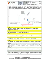
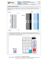
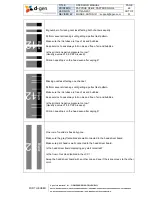
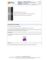
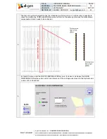
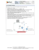
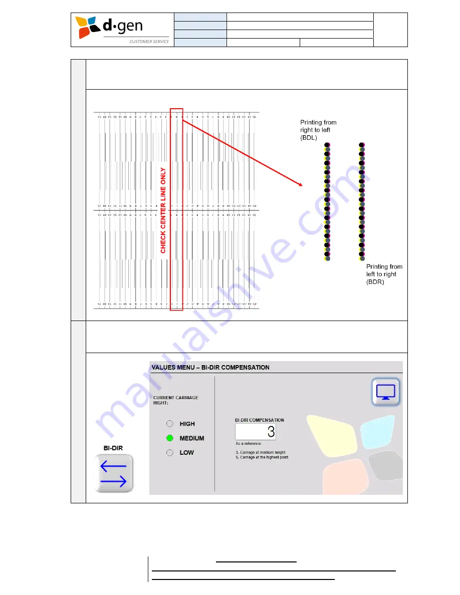
The test print will look something like the image below. Using a loop or a microscope is possible to 
check the middle line. If BDL and BDR are were not fired on the same spot means the bidirectional 
compensation factor needs to be corrected. 


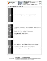
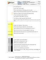
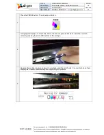
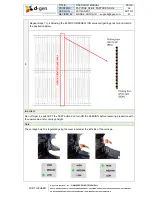
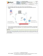
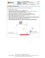
In VALUES menu enter the BI-DIR COMPENSATION screen. Increase or decrease the BI-DIR 
COMPENSATION value certain units. As a reference, if the carriage was moved to the highest point, 
a value of 5 is introduced. 


Summary of Contents for Papyrus G5/H4

Page 1: ...OPERATOR MANUAL ...

Page 2: ...ns electronic mechanical photocopying recording or otherwise without the prior written permission of d gen Inc International The information contained herein is designed only for use with this d gen printer d gen is not responsible for any use of this information as applied to other printers Neither d gen Inc International nor its affiliates assumes no responsibility to the purchaser of this produ...

Page 3: ...ysician if the skin appears irritated or is discolored If fluid enters your eyes rinse immediately with water Failure to observe this precaution could result in bloodshot eyes or mild inflammation If fluid enters your mouth consult a physician immediately If fluid is swallowed do not force the person to vomit and consult with a physician immediately If the person is forced to vomit fluid may get c...

Page 4: ...to print properly If you have not used the printer for a long time check the print head for clogging before you start printing Perform head cleaning if the print head is clogged When storing the printer be sure that it is level do not store it on an angle on end or upside down When handling the ink bottles Store the ink bottles at room temperature out of direct sunlight To ensure print quality use...

Page 5: ...downwards to the front dancing bar 4 Carriage cover This cover is opened for maintenance purposes such as manual purge of the print heads cleaning of the wipers and the capping station etc Normally closed when using the printer 5 Pinch roller lever With this lever is possible to move up down the pinch rollers when mounting unmounting or advancing the media Move the lever backwards to lift the pinc...

Page 6: ... Depending on the media s characteristics it is used either the heavier or lighter dancing bar INTERIOR CARRIAGE 1 Solenoid valves The solenoid valve is opened if the LED is turned on Having the solenoid valve opened allows free circulation of negative air pressure between the vacuum pump and the head Making the heads to bleed for long purging is possible by closing the solenoid valve LED switched...

Page 7: ... the machine in an emergency state if the carriage crashes against the right stopper 8 Right stopper This machine is provided with 2 side stoppers to prevent the carriage damaging the side limit sensors 9 Flushing stage The flushing unit is used to keep the print heads unclogged Every time the carriage leaves the home position for printing right to left the heads flush a very small quantity of ink...

Page 8: ...ectric panel Normally closed when using the printer 4 Rear rubber free roller With the rear control panel is possible to switch it ON OFF regulate the feeder s speed and mode 5 Negative Positive pressure system Behind this cover there are a series of pumps and valves that creates enough negative pressure in the heads for stable printing or enough positive pressure to purge the heads for cleaning i...

Page 9: ...tered ink to the print heads This filter needs to be replaced periodically or when changing the chemistry color of the ink 2 Ink LED indicator Two LED lights per color The red LED turns on when the level of ink in the Big Ink System is critically low Green LED is turns on if refilled Buzzer will sound to indicate low level of ink in one of the ink cylinders 3 Big Ink System K C M Y sensor level ca...

Page 10: ...7 Connector for SP1 and SP2 ink supply pumps This connector comes from the Ink Supply System board located in the rear electric panel Activates SP1 and SP2 ink pumps when the sub tanks are needed to be refilled 8 Connector for K C M Y ink supply pumps This connector comes from the Ink Supply System board located in the rear electric panel Activates K C M Y ink pumps when the sub tanks are needed t...

Page 11: ...over is opened for refilling the inks 4 Ink level photo sensor This photo sensor measures the ink level with a laser beam Keep this area always free of ink BIG INK SYSTEM BACK SIDE 5 White LED bar s power connector This cable powers up the white LED light bar in the Big Ink System 6 Ink outlets By pushing down the silver fastening is possible to release or insert the ink line without spilling ink ...

Page 12: ...printer Two at the front on each side Pushing one of the switches will bring a total stop the carriage and other moving elements 2 Open cover switch Opening either the front or carriage cover will activate the emergency switch bringing the carriage to a pause state returning to the home position Note In case the printer exceeds its operation limits such as over speed operational temperature etc th...

Page 13: ...ORIZED PERSONS PROHIBIDA SU DIVULGACIÓN A PERSONAS NO AUTORIZADAS DO NOT REPRODUCE WITHOUT AUTHORIZATION NO REPRODUCIR SIN AUTORIZACIÓN 4 TURNING ON AND OFF THE PRINTER Turning ON the printer The operator must follow the following steps to correctly turn ON the printer 1 Turn on the dryer printer s base 2 Turn on the printer by pressing the white switch at the back of it 3 Turn on the PC control b...

Page 14: ... A PERSONAS NO AUTORIZADAS DO NOT REPRODUCE WITHOUT AUTHORIZATION NO REPRODUCIR SIN AUTORIZACIÓN 4 Wait for the touch panel to display Jetting Turning OFF the printer Turn off the PC control box by pressing the green switch As soon as a beep is heard turn off the printer by pressing the white switch at the back of it Leave the dryer running with no heating To cool down the unit Once cooled turn of...

Page 15: ...O AUTORIZADAS DO NOT REPRODUCE WITHOUT AUTHORIZATION NO REPRODUCIR SIN AUTORIZACIÓN 5 LOADING INK The operator must follow the following steps to correctly load with ink the Big Ink System 1 Open the Big Ink System s cover Buzzer will be activated 2 Open the lid Make sure the filter is present and correctly positioned 3 Pour gently to avoid spilling ink outside the cylinder Do not pour the ink too...

Page 16: ...ÓN 4 Close the lid Do not close the lid too tight to let the air go into the cylinder as it gets empty when printing Important Do not wait until the cylinder gets completely empty Risk of clogging the ink filter damaging the heads with the deposited ink sediments at the bottom We strongly suggest to refill the tank as soon as the buzzer is heard Important When pouring ink foam will be created Do n...

Page 17: ...dgen com 51 FOR THE USER d gen International Inc COMPANY PRIVATE LEVEL 1 NOT TO BE DISCLOSED TO UNAUTHORIZED PERSONS PROHIBIDA SU DIVULGACIÓN A PERSONAS NO AUTORIZADAS DO NOT REPRODUCE WITHOUT AUTHORIZATION NO REPRODUCIR SIN AUTORIZACIÓN 6 LOADING THE MEDIA Introducing the printer s base control panel Feeder unit control panel ...

Page 18: ...1 FOR THE USER d gen International Inc COMPANY PRIVATE LEVEL 1 NOT TO BE DISCLOSED TO UNAUTHORIZED PERSONS PROHIBIDA SU DIVULGACIÓN A PERSONAS NO AUTORIZADAS DO NOT REPRODUCE WITHOUT AUTHORIZATION NO REPRODUCIR SIN AUTORIZACIÓN Take up unit control panel 1 Release the latches at both side of the feeding unit to remove the pneumatic shaft ...

Page 19: ...CE WITHOUT AUTHORIZATION NO REPRODUCIR SIN AUTORIZACIÓN 2 Press the golden valve to release all the air inside the pneumatic tube 3 Place the pneumatic shaft in the media s core oriented to make the printable side facing upwards when going through the printing table Make sure the roll is centered using the measuring tape as a reference 4 With the help of an air compressor only the air gun is provi...

Page 20: ...N NO REPRODUCIR SIN AUTORIZACIÓN 5 Lift the pneumatic shaft with the roll fastened and place it carefully in the feeder unit Insert back the latches at both sides of the feeder unit to safely secure the pneumatic shaft Using the rear control panel unwind a certain length of media to make it go through the rear dancing bar Depending on how the media s core is oriented push the MANUAL BWD or FWD to ...

Page 21: ...AS NO AUTORIZADAS DO NOT REPRODUCE WITHOUT AUTHORIZATION NO REPRODUCIR SIN AUTORIZACIÓN 7 Stop unwinding when the media reached a higher point than the free roller Make the media go through the free roller Make sure the media s edges are aligned with the jumbo roll installed in the feeder unit 8 Then make it go through the rubber roller Make sure the media is aligned by ensuring that the distance ...

Page 22: ...ers are lifted by moving the lever towards the back of the printer Send the media to the front Always keeping the media perfectly aligned with the printer s frame at all points Once the media is on the front side of the printer under tension a second person can lower the pinch rollers 10 Change the feeder to AUTO mode FWD The feeder unit will feed media until the rear dancing bar reaches its lowes...

Page 23: ...PERSONS PROHIBIDA SU DIVULGACIÓN A PERSONAS NO AUTORIZADAS DO NOT REPRODUCE WITHOUT AUTHORIZATION NO REPRODUCIR SIN AUTORIZACIÓN 11 Insert the media into the dryer Then advance the media pressing the feeding FWD button on the touch panel A second person will be on the printer s back side to grab the media s end 12 Once the media reached the other side of the dryer you may pause advancing media Ali...

Page 24: ...drying unit always free of intrusive elements Risk of fire Caution Please be careful not to trap your hands or fingers when opening or closing the front cover Failure to observe this precaution could result in injury Caution Secure the media in place by the following procedure Injury may occur if the media falls Caution Since the media is heavy it should not be carried by one person When loading o...

Page 25: ...nternational Inc COMPANY PRIVATE LEVEL 1 NOT TO BE DISCLOSED TO UNAUTHORIZED PERSONS PROHIBIDA SU DIVULGACIÓN A PERSONAS NO AUTORIZADAS DO NOT REPRODUCE WITHOUT AUTHORIZATION NO REPRODUCIR SIN AUTORIZACIÓN Caution After finishing installing the media please use the media guide plates on the bed plate to ensure the carriage will not hit the edges of the media ...

Page 26: ...UT AUTHORIZATION NO REPRODUCIR SIN AUTORIZACIÓN 7 NOZZLE CHECK TEST PRINT The nozzle check test print allows the user to check the current state of the nozzles in the print head Helps to determine if the nozzles are firing as they should or not Probably caused by dried ink or air in the system 1 Once the media is correctly loaded you may proceed to check the media s width by pressing the button ME...

Page 27: ...E USER d gen International Inc COMPANY PRIVATE LEVEL 1 NOT TO BE DISCLOSED TO UNAUTHORIZED PERSONS PROHIBIDA SU DIVULGACIÓN A PERSONAS NO AUTORIZADAS DO NOT REPRODUCE WITHOUT AUTHORIZATION NO REPRODUCIR SIN AUTORIZACIÓN 2 In VALUES MENU screen select test pattern number 1 and then press the TEST PRINT button to print the nozzle check test print ...

Page 28: ...S LIKE All the nozzles are firing correctly presenting no gaps in the test print A certain number of nozzles are not firing independently from which row number they belong to A certain number of nozzles may be clogged Perform several cleanings until getting a perfect test pattern Is the printer s negative pressure too high Usually a value of 3 50 KPA is used One or few couple of missing nozzles af...

Page 29: ...gative pressure too low Usually a value of 3 50 KPA is used Still can see drops on the head even after wiping it Missing nozzles affecting one channel Perform several cleanings until getting a perfect test pattern Make sure the ink tubes are free of air and bubbles Keep service hoses always full on ink and free of air and bubbles Is the printer s negative pressure too low Usually a value of 3 50 K...

Page 30: ...bled in the JCC Is the head driver board displaying any alert noise led Swap the head driver board with another one and see if the issue moves to the other color Another color is detected on the test pattern Perform several cleanings until getting a perfect test pattern Make sure the ink in the line is not contaminated with anther color Make sure the print head is not contaminated with another col...

Page 31: ... alignments were correctly performed BDR value should be the same in both row of nozzles 8 PURGE AND AUTO CLEANING There are 2 types of print head cleanings 1 Auto cleaning Performed by pressing the CLEANING button in the touch panel 2 Long purge Performed by pressing the PURGE button in the touch panel and close the solenoid valves to keep the positive pressure in the heads drip ink constantly Au...

Page 32: ...CIÓN A PERSONAS NO AUTORIZADAS DO NOT REPRODUCE WITHOUT AUTHORIZATION NO REPRODUCIR SIN AUTORIZACIÓN 1 Press the PURGE button The air pump will kick in 2 Giving approximately 3 to 5 seconds before the vacuum pumps kicks back close the solenoid valves by pressing the white LED buttons at the carriage 3 Keeping the positive pressure between the subtanks and the print heads it is possible to keep the...

Page 33: ...f the nozzles recovered Important Do not press the CANCEL button when purging ink Important The printer cannot purge or clean the print heads having one of the subtanks empty To purge or clean the print heads all subtanks must be full and displaying the JETTING message in the touch panel Important Every time before purging or cleaning the print heads verify the ink drain bottle is empty Note The i...

Page 34: ... media s thickness and or change the carriage height for whatever reason the bidirectional compensation factor needs to be regulated to make the heads fire exactly on the same spot when printing from right to left and left to right After changing the media s characteristics and or changing the carriage height is required to check if the machine is still aligned bidirectionally by printing test pat...

Page 35: ...ODUCE WITHOUT AUTHORIZATION NO REPRODUCIR SIN AUTORIZACIÓN 3 The test print will look something like the image below Using a loop or a microscope is possible to check the middle line If BDL and BDR are were not fired on the same spot means the bidirectional compensation factor needs to be corrected 4 In VALUES menu enter the BI DIR COMPENSATION screen Increase or decrease the BI DIR COMPENSATION v...

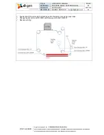
Page 36: ...CIÓN A PERSONAS NO AUTORIZADAS DO NOT REPRODUCE WITHOUT AUTHORIZATION NO REPRODUCIR SIN AUTORIZACIÓN 5 Repeat steps 1 to 4 adjusting the BI DIR COMPENSATION value until getting a test print similar to the illustration below Important Do not forget to switch OFF the TEST button and turn ON the FEEDING before resuming production with the new media and or carriage height Note The carriage height is r...

Page 37: ...help to obtain good quality prints without having feeding banding issues There are two steps to adjust the feeding First before start to print is recommended to take a look at the speed dials located at the take up and feeder units Then while printing through the touch panel is possible to adjust the feeding correction more precisely When turning at same speeds an empty roll will turn less distanc...

Page 38: ...l press the VALUES button and then proceed to press the minus button as many times needed until no distance between passes can be seen Dark band between passes Means the feeding system has to feed more distance while printing in order to eliminate the overlap between passes To increase the feeding compensation in the touch panel press the VALUES button and then press the plus button as many times ...

Page 39: ...UCIR SIN AUTORIZACIÓN Front dancing bar s weight Depending on the media s characteristics we suggest to use either the light grey or heavy black front dancing bar The purpose is before printing have the dancing bars applying the correct tension to the media without breaking it or destabilizing the feeding system To change the front dancing bar just pause cancel the print release the latches at bot...

Page 40: ...te the speed of the fans by pressing the high or low button at the control panel If it is not enough just by using fan power you may turn on the 8 heating rods and the front rubber heater by turning ON HEATER 1 Possible to regulate the temperature by using the thermostat Usually is used a temperature between 60 to 90 C 140 to 194 F Check if the printed images at the take up roll are dried enough I...

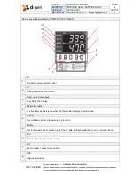
Page 41: ...CIR SIN AUTORIZACIÓN How to use the thermostat AUTONICS TZ4ST SERIES 1 PV Processing value indicator Red 2 SV Setting value indicator Green 3 Move up and down keys Key shifting the display 4 Information table Use this table as a reference when the thermostat displays a certain code 5 AT key This mode key turns on the auto tuning function 6 MD key This is the mode key Is pressed to set the SV after...

Page 42: ...hile Auto tuning is being executed 11 SV2 Is turned on when SV2 is operating Note To set the temperature in the thermostat just press the left arrow Then change the value by using the up and down arrows Once got the desired value you may press the MD button to set the target temperature SV Caution The drying unit may be hot observe all necessary precautions Failure to observe the necessary precaut...

Page 43: ...er Release the latches at both side of the feeding unit to remove the pneumatic shaft Press the golden valve to release all the air inside the pneumatic tube Remove the pneumatic shaft from the media s core Place the pneumatic shaft in the new media s core orientating the printable side upwards when going through the printing table With the help of an air compressor only the air compressor gun is ...

Page 44: ... units Feeder and take up at AUTO FWD mode Press the forward button in the touch panel to move the union to the front side after passing the carriage Once the union is about half way between the front roller and the front dancing bar you may stop the media feeding Make sure the printing table is free of wrinkles and place back the media guide plates Resume printing Important We recommend the use o...

Page 45: ...o lower the front dancing bar MANUAL BWD Once the front dancing bar is in the lowest point you may cut the media Release the latches at both sides of the take up unit to remove the pneumatic shaft Remove the roll with the help of a roll lifter If not 2 persons is required for this operation Press the golden valve to release all the air inside the pneumatic tube Remove the pneumatic shaft from the ...

Page 46: ...ternational Inc COMPANY PRIVATE LEVEL 1 NOT TO BE DISCLOSED TO UNAUTHORIZED PERSONS PROHIBIDA SU DIVULGACIÓN A PERSONAS NO AUTORIZADAS DO NOT REPRODUCE WITHOUT AUTHORIZATION NO REPRODUCIR SIN AUTORIZACIÓN Feed a little bit more media to attach its end to the empty core using paper tape Change feeder unit to AUTO FWD and Take up unit to AUTO FWD Resume printing ...

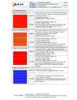
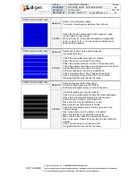
Page 47: ...ressure may be unstable ACTION Perform a test print pattern number one Check for clogged nozzles Check for air in the system Check if the negative pressure is too low Perform several cleanings until getting a perfect test print Service hoses must be filled with ink No air in them PRINT LOOKS LIKE THIS REASON Intermittent nozzles For example yellow lines can be seen on a red area after an indetermi...

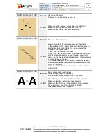
Page 48: ... is correct in the dancing bars Check the speed at the take up and feeding units are similar and equilibrated not too fast or too slow Perform a feeding motion K value calibration Check correct tension in the Y feeding timing belts Check no feeding pulley lost traction from the shaft Using optimization may resolve the issue PRINT LOOKS LIKE THIS REASON Some passes are lighter than others Chromatic...

Page 49: ...ure to change the bi directional compensation factor to 5 when moving the carriage to the highest point Is the tension in the media too low If media is stored inappropriately or left loaded in the printer wrinkles and waviness may occur If media is used in this state the print head and the raised surface of the media may contact and cause staining If the media loading method heating temperature te...

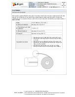
Page 50: ...efer to the documentation supplied with the media or contact the manufacturer We recommend that you print a test run and check the results before purchasing media in large quantities Width 297 to 1880 mm 11 6 to 74 A Roll outer diameter Maximum 350 mm 13 7 B Paper pipe core inner diameter 76 2 mm 3 C Media thickness Maximum 2 5 mm 1 10 Roll weight Maximum 150 kg 331 lb Unavailable conditions Media...

Page 51: ...nformation on the installation configuration and operation of professional printing products through this email address support dgen com and telephone number 82 32 510 3503 from 8 30 AM to 5 30 PM Korea Standard Time UTC 9 00 Monday through Friday When sending an email please write the title of the email as follows Name of the company Printer Model Printer serial number Issue When contacting by ph...

Reviews: