12/36
CPS-M1-MSE
4
4
3
3
2
2
RJ12
1
1
CM-BT1-D4-P2
TP-C1
NO 1
NO 2
NC 1
NC 2
COM 2
n.c.
n.c.
5
1
1
4
2
2
3
3
3
2
1
DI 1.3
ACN D+
ACN D+
DI 1.2
ACN D-
ACN D-
DI 1.4
–
n.c.
Shield
Shield
X1
X2
X3
X6
X5
X4
COM 1
TP-C1-35-RJ12
X1.1
X1.4
X2.1
X2.4
X3
X4.3
X5.3
X6.5
X6.1
X4.1
X5.1
X1
X6
X2
X5
X4
X3
English
99.828.70 1.2/07/22
No.
Name
Description
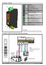
X1.1 n.c.
n.c.
X1.2 NO 1
Isolated change-over contact, max. 35 V / 1 A,
collective alarm (factory setting, can be pro-
grammed using SCS)
X1.3 COM 1
X1.3 NC 1
X2.1 n.c.
n.c.
X2.2 NO 2
Isolated change-over contact, max. 35 V / 1 A,
general malfunction (factory setting, can be pro-
grammed using SCS)
X2.3 COM 2
X2.4 NC 2
X3
TP-C1
RJ12 connection for touch panel
X4.1
Shield
AdComNet master interface
X4.2
ACN D-
X4.3
ACN D+
X5.1 Shield
AdComNet slave interface
X5.2 ACN D-
X5.3 ACN D+
X6.5 n.c.
n.c.
X6.4 DI 1.2
Freely configurable digital input,
0 to 28 V, active minus or plus,
control panel OPEN (factory setting, can be pro-
grammed using SCS)
X6.3 DI 1.3
Freely configurable digital input,
0 to 28 V, active minus or plus,
control panel CLOSED (factory setting, can be
programmed using SCS)
X6.2 DI 1.4
Freely configurable digital input,
0 to 28 V, active minus or plus
X6.1 -
Reference potential (do not connect to P-)
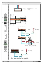
Connection – CM
* Termination:
Every segment must be
terminated with 2 resistors
(110 Ω).
The resistors must be
connected as far apart as
possible.
Connections that are not used
also have to be terminated!
Isolated change-over contacts, max. 35 V / 1 A,
(factory settings, can be programmed using SCS)
Collective alarm
General malfunction
Freely configurable
digital inputs
Central OPEN
Central CLOSE
Earth the
shielding
once per segment.
RJ12 connecting cable
CC-TP/TCSU
Relay de-en-
ergizes on
fault
Relay
energizes
on alarm


