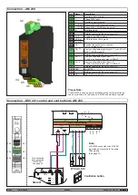
13/36
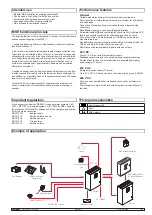
CPS-M1-MSE
CM / AM / TMA / IOM
DI x.1
–
–
DO x.1
24 V DC
CM
PSM
AM
AM
TMA
TMA
CM
PSM
AM
AM
TMA
TMA
CM
PSM
AM
X4.3
X5.3
X5.3
X4.1
X5.1
X5.1
ACN D+
ACN D-
Shield
ACN D+
ACN D-
Shield
English
99.828.70 1.2/07/22
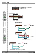
Connection – Digital inputs and outputs
Contact
Inverted
Signal
Open
Off
0
Closed
Off
1
Open
On
1
Closed
On
0
active minus
˄
either
˅
active plus
Digital inputs
Digital outputs
24 V DC
Each max. 50 mA
(programmable using SCS)
Battery for the clock of the event memory
The CM module has a built-in lithium battery on the underside, which
buffers the internal clock of the event memory in the event of a power
failure.
The battery should be replaced at least every 10 years.
Attention! Folgende Reihenfolge beachten:
1. Read out and save existing parameterization
2. Change battery. Battery type: Lithium cell CR1216
3. Read in parameterization again
* Termination:
The AdComNet segment must
be terminated with 2 resistors
(110 Ω).
The resistors must in each case
be connected at the end of the
cable.
Connections that are not used
also have to be terminated!
Earth the segment
shielding once.
Further top hat rail levels for additional CPS-M modules
If a top-hat rail is not sufficient for the configuration of your system, a further top-hat rails can be integrated in the following way.
Further top-hat rail rows are assembled like the first row of the CPS-M (see
« Arrangement of the modules » page 8 )
Connect the AdComNet master interface X4 on the CM module of the first row to the AdComNet slave interface X5 on the CM module of the
additional row. If you need additional module rows, proceed in the same way.
You can connect to any CM via USB and use the connected rows as a common control panel.
LT inputs, lines and groups can be freely linked across all rows.


