3/36
CPS-M1-MSE
English
99.828.70 1.2/07/22
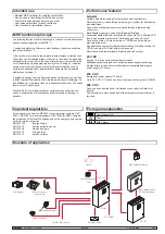
Intended use
•
Modular MSE controller for complex control tasks
•
Can be used in the AdComNet SHEV bus system
•
Combine lines and groups however you want
• Convenience functions for daily ventilation
• Only intended for installation indoors
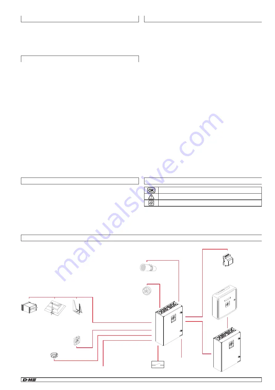
Example of application
Pictogram explanation
Control panel O.K.
Fault
SHEV alarm
MSE functional principle
The following functions run simultaneously in the event of smoke detection
and subsequent triggering of the MSE. 1:
1. supply and discharge After successful feedback, the smoke extraction
fans are switched on. 2.
2. the smoke is removed via temperature-resistant smoke extraction fans.
These fans can be installed either on the roof, in the wall of the respective
utilisation units or centrally. In the case of interior rooms, the smoke is led
out of the building via an appropriate duct system. In doing so, it must be
ensured that the smoke does not re-enter adjacent utilisation units. To
avoid this undesirable effect, appropriate fire dampers can be installed
within the duct system. 3.
3. postflow openings near the floor are opened so that supply air can flow
in at the required flow velocity within the low-smoke layer accordingly. If a
free afterflow is not possible, fresh air is supplied mechanically. The smoke
layer must not be destroyed.
Practical tip: For the implementation of complex smoke extraction sce
-
narios, a combination of mechanical and natural supply air tracking is
possible.
Important regulations
It is necessary to observe VDE 0833 for danger alarm systems, VdS
2221, VDE 0100 for electrical systems, DIN 18232 for SHEV systems,
the provisions of the local fire brigade and of the energy supply compa
-
ny for the mains connection.
EN 12101-10
Energy supply
EN 12101-7
Smoke extraction ducts
EN 12101-8
Smoke dampers
EN 12101-3
Fire gas fans
EN 12101-1
Smoke curtains
Performance features
General
Variable module technology for complex control requirements
Flexible system structure through mounting rail system for all modules
and extensions
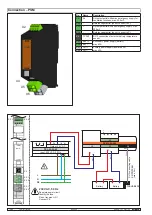
Connection of supply and communication through integrated plug
connectors
Retrofittable modules in case of building modifications
Parameterisable MRA and ventilation functions via D+H Software SCS
Inputs and outputs monitored for line breakage and short circuit
Connection of max. 30 fire detectors or 10 MRA control points per
monitored line input
AdComNet bus system for seamless networking of modules within the
CPS-M and other D+H AdComNet components
Flexible use of parameterisable, digital inputs and outputs
24 V DC
2x max. 10 A drive current per actuator module
Stabilised output voltage due to switching power supply technology
No signal loss in case of mains failure due to integrated emergency
power supply (72 hours)
230 V AC
Emergency power supply (72 hours)
Up to 45, 230 V AC drives can be connected per drive group (1840VA)
400 V AC
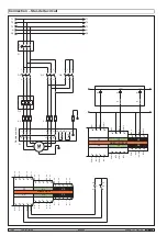
Fans can be controlled either via frequency converter, soft starter or
directly.
Power supply via main switch and with automatic mains switchover if
required.
OK
External control
CO, NO, LPG sensors
MSE operation panel
Smoke detector
Drives for intake
air opening
Fire damper
Smoke extraction
fan
Jetfan
CCS / BMS
Line
Group
CPS-M
CPS-M
KNX, Modbus gateway
AdComNet enable
D+H control panel
AdComNet
400V AC


