background image

99.827.73 1.0/10/18

VCD-0203-1-ACB-R

VCD-0203-1-ACB-R

6/16

7/16

99.827.73 1.0/10/18

English

English

Closing edge protection

In  the  "CLOSE"  direction  the  drive  has  an  active 
protection for the main closing edge. If there is an 
overload in the closing ranges C3 and C2, the drive 
runs "OPEN" for 10 seconds, then "CLOSE" again. If 
closing is not possible after three attempts, the drive 
remains in this position.
In  addition,  the  drive  is  equipped  with  passive 
protection.  The  closing  speed  in  closing  range  C2 
and C1 is reduced to 5 mm/s.


  Significantly greater forces can be


  exerted at the secondary closing


  edges. Danger of crushing hands and


  fingers!

Main closing edge

Beside closing edge

Beside closing edge

C3*

200 N

Opening and Closing Ranges

O1*

C1*

C2*

O2*

O3*

23 mm

150 N

77 mm

150 N

23 mm

200 N

15 mm

200 N

200 N

Technical Data

* Programmable with software SCS   ** + approx. 20 % switch-off reserve (temporary)

Type

VCD-0203-0250-1-ACB-R

Power supply
Nominal force

24 V DC / ± 20 %
200 N**

Nominal current

0,35 A

Nominal stroke length*

250 mm 

±

 2 %

Running speed:
O1, O2
O3
C3
C2, C1

 
6 mm/s
5 mm/s
6 mm/s
5 mm/s

Nominal locking force
Service life
Duty cycle
Housing
Ingress protection
Temp. range
Ambient humidity
Emission sound pressure level
Additional functions*

approx. 2000 N (Excluding bracket)
>20.000 double strokes
30 % (With cycle time 10 minutes)
Zinc-diecasting powdercoated (~ RAL 9006)
IP 30
0 ... +60 °C
≤ 90 %, not condensing
LpA ≤ 46 dB(A)
Closing edge protection = activated (3 repetitions of stroke);
Locking relief  = activated (retraction lift max. 0,2 mm)

ACB interface

Modbus RTU / RS 485, 19.200 bps, 8 data bits, 1 stop bit, parity: even

-  The drive set is fully configured ex factory.The 

drives must be reconfigured using the software 
SCS in the event of changes to the ex-factory 
configuration (e.g. when removing a drive from 
existing set or integrating a new drive).

-  Mount the drives whilst under zero stress. With 

that, an even load distribution is provided by all 
the drive chains.

-  At vertical active pulling application (e.g. for a 

skylight) the forces must be rearranged by 
software SCS.

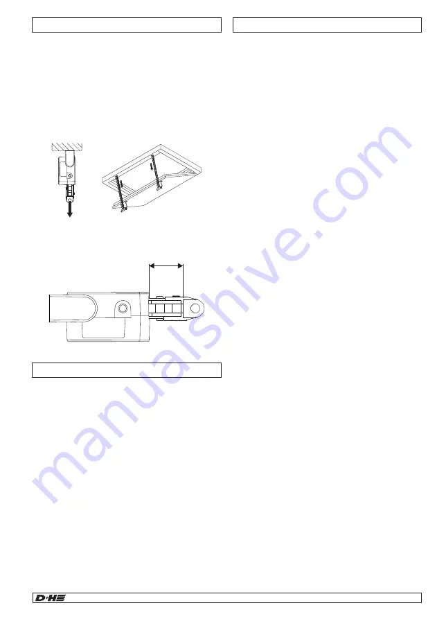
-  If after mounting, the distance X is greater than 23 

mm, null balance with software SCS is neccesary. 
Closure  Ranges  will  shift  in  relation  to  new  zero 
point.

Mounting information

ACB interface

ACB is used for secure communication between 
the drive and compatible D+H control systems. It 
enables activation, diagnostics and configuration 
with perfect position, directly from the control 
panel. In this process, all status messages, such 
as the OPEN and CLOSED signals, opening 
stroke and drive errors are transmitted to the 
control panel.
The ACB bus is based on an open Modbus RTU 
protocol via which the actuator can be directly 
controlled and queried.
Further information can be found in the D+H ACB 
Planning Manual.

BSY+ synchronised electronics:

A synchronous group can contain up to 8 drives, 
which communicate via bus. Each drive has its 
own address, configurable with SCS.
The last drive of a synchronous group is the 
master, which controls the other drives, the slaves. 
Differences in forces between the drives of a group 
are balanced by means of intelligent force and 
position control. In the event that a drive 
malfunctions, all the drives are automatically cut 
off.
In addition, up to 4 BSY+ lock drives  and modules 
can be connected.

Functional description

Visual inspection: 

Only one master drive is allowed.
The master always has the last address of all the 
drives; this can be found on a sticker attached to 
the drive. Slaves are numbered downwards from 
the master, so that in a group of three drives, for 
example, the master is no. 3, with a slave 2 and 
slave 1 drive. Please note that this only applies in 
the ex-factory configuration. As soon as the drives 
are reconfigured with SCS, the ex-factory 
addressing no longer applies.

Wiring:

Is the drive or drive group wired properly?
See connection plans.

Diagnostics with SCS software:

The SCS software and a BSY+ interface is 
required for further troubleshooting or 
configuration.

Troubleshooting

≥ 23 mm ? 

X

Summary of Contents for VCD-0203-0250-1-ACB-R

Page 1: ... de fixation Rogamos que pidan los juegos de fijación por separado de Originalbetriebsanleitung Seite 2 Anschluss Seite 14 15 Abmessungen Seite 16 en Original instructions Page 5 Connection Page 14 15 Dimensions Page 16 fr Notice originale Page 8 Connexion Page 14 15 Dimensions Page 16 es Manual original Página 11 Conexión Página 14 15 Dimensión Página 16 ...

Page 2: ...der Einhaltung der nachfolgenden Anweisungen können elektrischen Schlag Brand und oder schwere Verletzungen verursachen Bewahren Sie alle Sicherheitshinweise und Anweisungen für die Zukunft auf Konformitätserklärung Wir erklären in alleiniger Verantwortung dass das unter Technische Daten beschriebene Produkt mit den folgenden Richtlinien übereinstimmt 2014 30 EU 2014 35 EU Technische Unterlagen be...

Page 3: ...en deutlich höhere Kräfte auftreten Quetschgefahr im handzugänglichen Bereich Technische Daten Programmierbar mit Software SCS ca 20 Abschaltreserve kurzzeitig Typ VCD 0203 0250 1 ACB R Versorgung Nenn Kraft 24 V DC 20 200 N Nenn Strom 0 35 A Nenn Hublänge 250 mm 2 Laufgeschwindigkeit O1 O2 O3 C3 C2 C1 6 mm s 5 mm s 6 mm s 5 mm s Nenn Verriegelungskraft Lebensdauer Einschaltdauer Gehäuse Schutzart...

Page 4: ...önnen bis zu 4 BSY Riegelantriebe sowie Module angeschlossen werden Funktionsbeschreibung Das Antriebsset ist vom Werk aus eingestellt Bei Veränderungen des Auslieferzustandes wie z B Antriebe aus bestehendem Set herausnehmen bzw neu eingliedern müssen die Antriebe mit der Software SCS neu programmiert werden Antriebe mechanisch spannungsfrei montieren Hierdurch wird eine gleichmäßigere Lastvertei...

Page 5: ...es Individually programmable via software SCS Protection system for the main closing edge Relief of pressure on window gasket after closing Electrical devices accessories batteries and packa ging should be sorted for environmental friendly recycling Do not dispose electrical devices and batteriesinto householdwaste Only for EC countries According the European Guideline 2012 19 EU for waste electri...

Page 6: ...and Closing Ranges O1 C1 C2 O2 O3 23 mm 150 N 77 mm 150 N 23 mm 200 N 15 mm 200 N 200 N Technical Data Programmable with software SCS approx 20 switch off reserve temporary Type VCD 0203 0250 1 ACB R Power supply Nominal force 24 V DC 20 200 N Nominal current 0 35 A Nominal stroke length 250 mm 2 Running speed O1 O2 O3 C3 C2 C1 6 mm s 5 mm s 6 mm s 5 mm s Nominal locking force Service life Duty cy...

Page 7: ...ctly controlled and queried Further information can be found in the D H ACB Planning Manual BSY synchronised electronics A synchronous group can contain up to 8 drives which communicate via bus Each drive has its own address configurable with SCS The last drive of a synchronous group is the master which controls the other drives the slaves Differences in forces between the drives of a group are ba...

Page 8: ... précise de 8 moteurs maximum Programmation individuelle à l aide du logiciel SCS Système de sécurité sur l arête de fermeture principale Relâchement de la contrainte sur joints après la fermeture Déclaration de conformité Nous déclarons sous notre propre responsabilité que le produit décrit sous Caractéristiques tech niques est enconformitéaveclesréglementationssuivants 2014 30 EU 2014 35 EU Doss...

Page 9: ... Arête de fermeture latérale C3 200 N Plages d ouverture et de fermeture O1 C1 C2 O2 O3 23 mm 150 N 77 mm 150 N 23 mm 200 N 15 mm 200 N 200 N Caractéristiques techniques Programmable avec le logiciel SCS env 20 de réserve de coupure En peu de temps Type VCD 0203 0250 1 ACB R Alimentation Force nominale 24 V DC 20 200 N Courant nominale 0 35 A Course nominale 250 mm 2 Vitesse de marche O1 O2 O3 C3 ...

Page 10: ...es informations dans le manuel de planification D H ACB BSY système électronique de synchronisation Un groupe de synchronisation peut se composer de maximum 8 moteurs qui communiquent par le biais d un bus Chaque moteur possède sa propre adresse laquelle est configurable à l aide du logiciel SCS Le dernier moteur d un groupe de synchronisation est le maître Master lequel pilote les autres moteurs ...

Page 11: ...ectrónico BSY para la marcha sincronizada segura y precisa de hasta 8 accionamientos Programación individual mediante el software SCS Protección systeme en canto principal de cierre Aligera la presión sobre las juntas al final del proceso de cierre Declaramos bajo nuestra responsabilidad que el producto descrito bajo Datos técnicos está en conformidad con las regulaciones 2014 30 EU 2014 35 EU Exp...

Page 12: ...erre secundario C3 200 N áreas de abertura y de cierre O1 C1 C2 O2 O3 23 mm 150 N 77 mm 150 N 23 mm 200 N 15 mm 200 N 200 N Datos técnicos Programable con el software SCS aprox 20 de reserva de desconexión Temporal Tipo VCD 0203 0250 1 ACB R Alimentación Fuerza nominal 24 V DC 20 200 N Corriente nominal 0 35 A Carrera nominal 250 mm 2 Velocidad de marcha O1 O2 O3 C3 C2 C1 6 mm s 5 mm s 6 mm s 5 mm...

Page 13: ...e el sotware SCS Si al finalizar el montaje la cota X es igual o superior a 23 mm será necesario un nuevo ajuste del punto cero mediante el sotware SCS Los rangos de cierre se decalan de manera relativa con relación al nuevo punto cero Instrucciones de montaje ACB interfaz Comunicación segura entre el accionamiento y los mandos D H compatibles a través del bus ACB Permite un control con posición e...

Page 14: ...3 1 ACB Abzweigdose Junction box Boîte de dérivation Caja de conexión BSY Master BSY Slave s GN GN BSY b BSY b YE YE BSY a BSY a 110 Ω PK ACB a GY ACB b GY ACB b PK ACB a CPS M AM VMC Terminierung Termination Terminaison Terminación Das ACB Segment muss mit 2 Widerständen 110 Ω terminiert werden Die Widerstände werden jeweils am Ende der Leitung angeschlossen The ACB segment must be terminated wit...

Page 15: ...o de la central Anschluss Connection Raccordement Conexión Zentrale Control panel Centrale Central RZN GVL Mot b BN Mot a WH 24 V DC 24 V DC WH Mot a VCD 0203 1 ACB GN BSY b BSY Master YE BSY a GY ACB b PK ACB a BN Mot b Modbus RTU RS485 Siehe auch ACB Planungshandbuch See also ACB planning manual Voir aussi Manuel de planification ACB Véase también el manual de planificación ACB 110 Ω 1 2 3 4 5 L...

Page 16: ...mmersbek 49 239 Tel 40 605 65 49 Fax 40 605 65 254 E Mail info dh partner com www dh partner com 2018 D H Mechatronic AG Ammersbek Technische Änderungen vorbehalten Rights to technical modifications reserved Sous réserve de modifications techniques Derecho reservado a modificaciones técnicas 100 Recyclingpapier Recycled paper Papier recyclé Papel reciclado ...

Reviews: