CDN36X User Manual
revision 1.30
CDN367 (2-WIRE RS485 configuration)
PIN
SIGNAL DESCRIPTION
1
RXA
RS485 differential data I/O signal.
2
RXB
RS485 differential data I/O signal.
3 TR
Internal
120
Ω
Terminating Resistor, connected between pins 1 and 3. Connect
pin 2 to pin 3 to terminate DATA signals. Use at end of long twisted-pair cable.
4
NC
No Connect. Do not connect any wires to NC pins.
5 GND
Ground.
6
TXA
Connect to pin 1 for 2-wire operation.
7
TXB
Connect to pin 2 for 2-wire operation.
8 TR2
Internal
120
Ω
Terminating Resistor, connected between pins 6 and 8. Do not
connect in 2-wire operation.
9
+5VDC
Auxiliary 5VDC supply generated by CDN36X.
CDN367 (4-WIRE RS422 configuration)
PIN
SIGNAL DESCRIPTION
1
RXA
RS422 differential receive data input signal.
2
RXB
RS485 differential receive data input signal.
3 TR
Internal
120
Ω
Terminating Resistor, connected between pins 1 and 3. Connect
pin 3 to pin 2 to terminal RX signals. Use at end of long twisted-pair cable.
4
NC
No Connect. Do not connect any wires to NC pins.
5 GND
Ground.
6
TXA
RS422 differential transmit data output signal.
7
TXB
RS422 differential transmit data output signal.
8 TR2
Internal
120
Ω
Terminating Resistor, connected between pins 6 and 8. Connect
pin 7 to pin 8 to terminate TX signals. Use at end of long twisted-pair cable.
9
+5VDC
Auxiliary 5VDC supply generated by CDN36X.
Wiring Examples
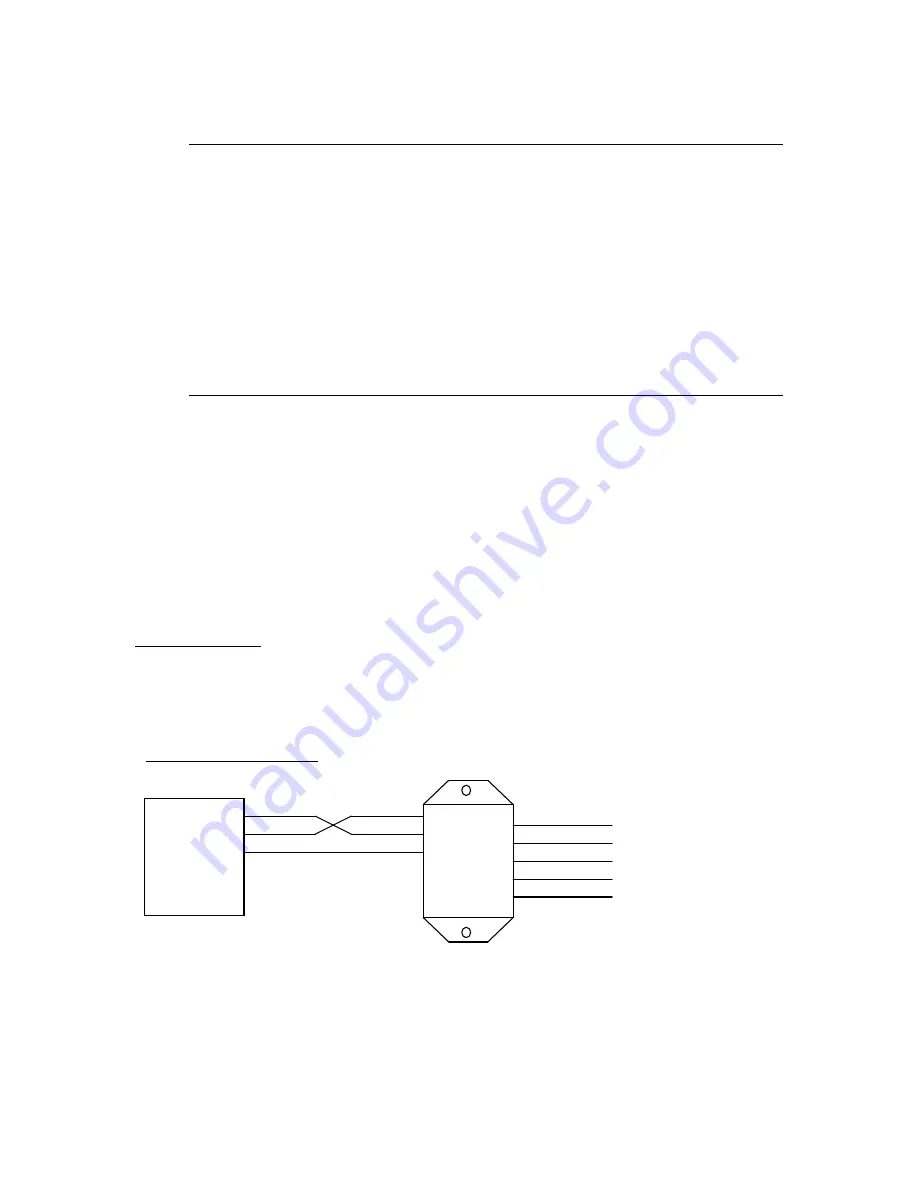
The following are typical CDN36X gateway wiring configurations. Your RS232 or RS422/485
interface may vary. Refer to your device’s documentation for the required data and control
signals.
CDNx66
2
3
5
RXD
TXD
GND
1
2
3
4
5
DRAIN
VDC+
VDC-
CAN H
CAN L
RXD
TXD
GND
2
3
5
RS232
Serial
Device
Simple RS232 Interface
MKS Instruments, Inc.
D.I.P. Products Group
7


