background image

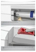
Step 5: Mark at least 3 fixing points on the packer approx. 100 mm from the top and bottom and distribute the 
holes approx. 400~500 mm apart making sure you place the holes over the bullnose (the highest point on the 
timber). 

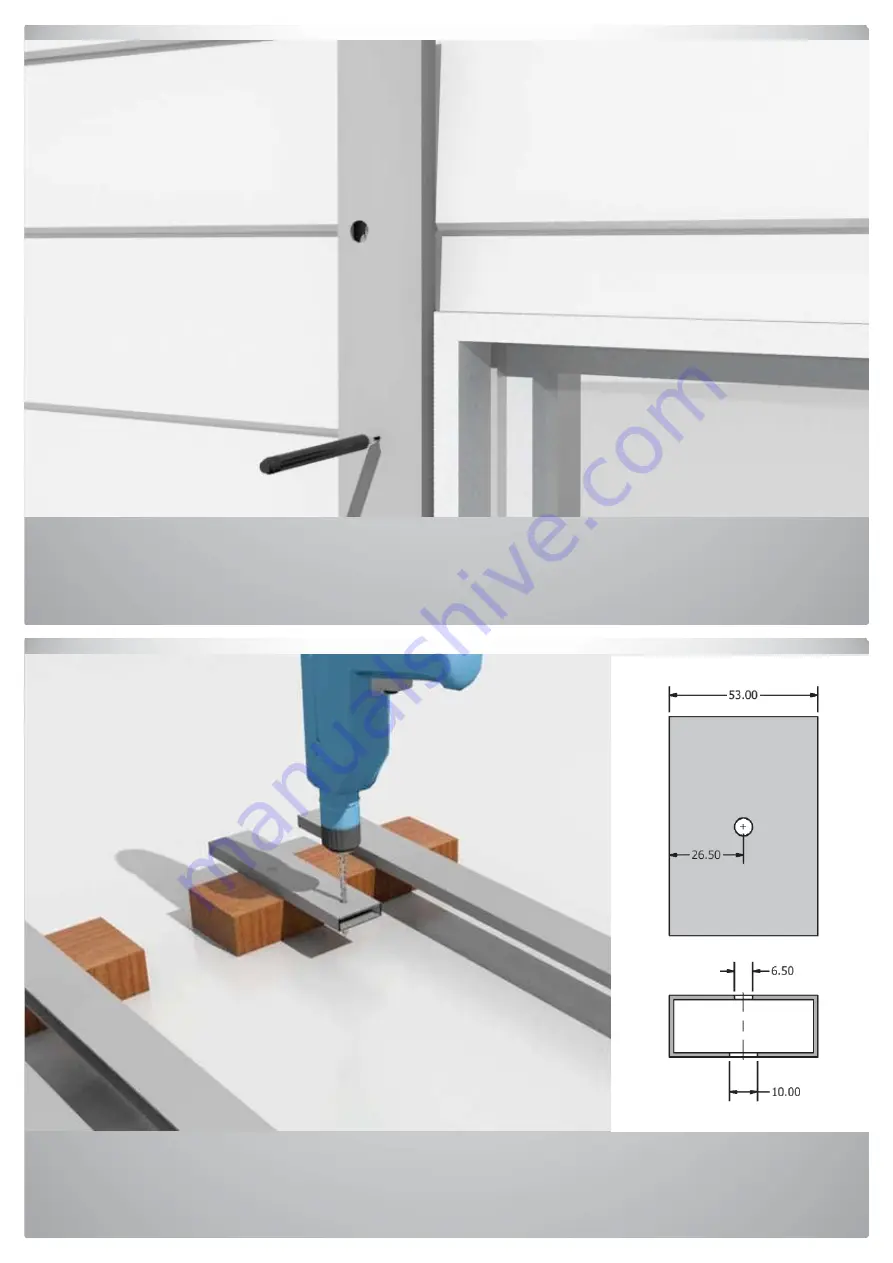
Step 6: Put the packer back on the ground and use the 6.5 mm drill bit to drill the holes all the way through on 
the points you have marked. Do the same on the other the packer. 

Summary of Contents for EZY-FIT DIY

Page 1: ...IY Roller Shutters Installation Instructions Face Fit Weatherboard Wall AC Electric Motor with Packer Videos and instructions available on our website http www ezyfitrollershutters com au Free call 1800 633 136 ...

Page 2: ...This page is intentionally left blank ...

Page 3: ...le if needed 2 Control switch 1 Tek screws if using packing profile 12 Wood screws 12 Hole caps 12 Pop rivets 3 2 mm 6 Height limit adjustment tool for motor 1 Wiring instructions 1 Paper template 1 Required tools not included 6 5 mm drill bit 1 10 mm drill bit 1 12 mm drill bit 1 Rivet gun 1 Cordless drill driver 1 Philips screw driver or Driver bit 1 Weatherboard walls with AC Electric Motor ...

Page 4: ...e instructions are designed for you to easily install your roller shutter using simple tools However call us on 1800 633 136 if you are in any doubt about how to install and operate the roller shutter or about any safety issues The wiring of 240 V AC Electric Motors should be conducted by a qualified electrician according to local and national standards and regulations Wear personal protective equ...

Page 5: ...1 Unwrap the pelmet box guides and packing profiles and put them on the ground Step 2 Remove the front cover by sliding it out ...

Page 6: ...Step 3 Make sure the end plate legs are in place on both sides If not slide them in place Step 4 Place one of the packers on the wall keeping it flush with the bottom of the opening ...

Page 7: ...tribute the holes approx 400 500 mm apart making sure you place the holes over the bullnose the highest point on the timber Step 6 Put the packer back on the ground and use the 6 5 mm drill bit to drill the holes all the way through on the points you have marked Do the same on the other the packer ...

Page 8: ...change the drill bit to 10 mm and ONLY drill through the front part of packer on all holes Do not drill all the way through Step 8 Put one of the packers next to the shutter guides keeping them level at the bottom ...

Page 9: ...op and bottom and distribute the holes approx 400 500 mm apart making sure they don t overlap with the packer s holes drilled in the packers Step 10 Use the 10 mm drill bit and ONLY drill through the front part of the shutter guides on marked positions Do not drill all the way through ...

Page 10: ...Step 11 Put one of the packers on the wall and mark the holes on the wall Step 12 Use the 3 mm drill bit to drill pilot holes for securing points including the pelmet box fixing point ...

Page 11: ...the provided screws Step 14 Put the other packer on the wall and space it so that the overall measurement of the packers is the same as the overall width of the pelmet box Measure the top and bottom distance to make sure the packers are parallel ...

Page 12: ...Step 15 Mark all the holes for the securing points on the wall Step 16 Use the 3 mm drill bit to drill pilot holes for securing points ...

Page 13: ...Step 17 Secure the packer on the wall using the provided screws Step 18 Slide the shutter guides onto the end plate legs and secure them with the supplied rivets in the pre drilled holes ...

Page 14: ...ill angle is required secure the sill angle with supplied rivets in the pre drilled holes Step 20 Shutter is now ready to be secured on the wall Put one hand underneath the pelmet box and the other holding the shutter guide Avoid tilting the guides as this may break the legs ...

Page 15: ...ft at the same time to place it on the wall Then slide it up in place while pushing against the wall Step 22 Use the provided TEK screws and a drill driver to secure the shutter guides on the packers Note TEK screws are self drilling screws and don t need additional holes pre drilled before use ...

Page 16: ...After putting all the screws in use the plastic caps to cover the holes Step 24 Roller shutter is installed now Ask a Qualified Electrician to wire the AC motor for you according to the provided wiring diagram ...

Page 17: ...Step 25 With the shutter closed secure the pelmet box Step 26 Put the front cover in place by sliding it in and securing it using the provided rivets into the pre drilled holes ...

Page 18: ...Step 27 Enjoy your roller shutter ...

Reviews: