10BASE-T Stackable Hubs
2
2
E
XTERNAL
F
EATURES
AND
I
NDICATORS
This chapter introduces the controls and connectors on the front and rear
panels of the hub, and explains the front panel display in detail.
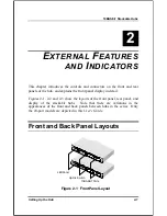
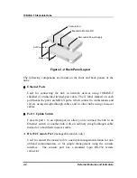
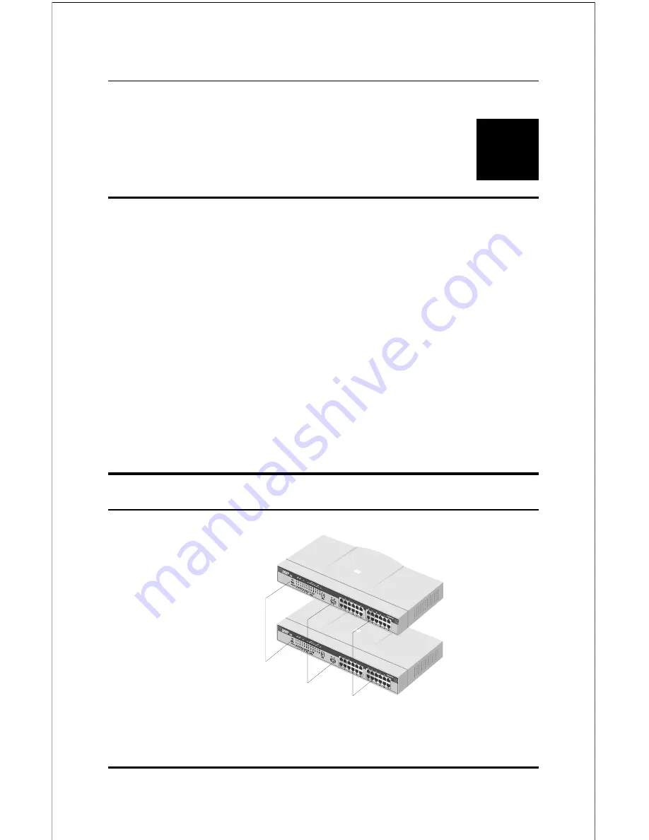
Figures 2-1, 2-2 and 2-3 show the layouts of the front panel, rear panel, and
display of the stackable hubs. Note that there are variations in the
appearances of the front and back panels between hubs in the series. Only
the 24-port models are depicted in this
User's Guide
.
Front and Back Panel Layouts
Uplink Sw itch
10BASE-T Ports
LED Panel
Figure 2 -1 Front Panel Layout
Setting Up the Hub
2-1


