background image

0110562R4 Page 3 of 8

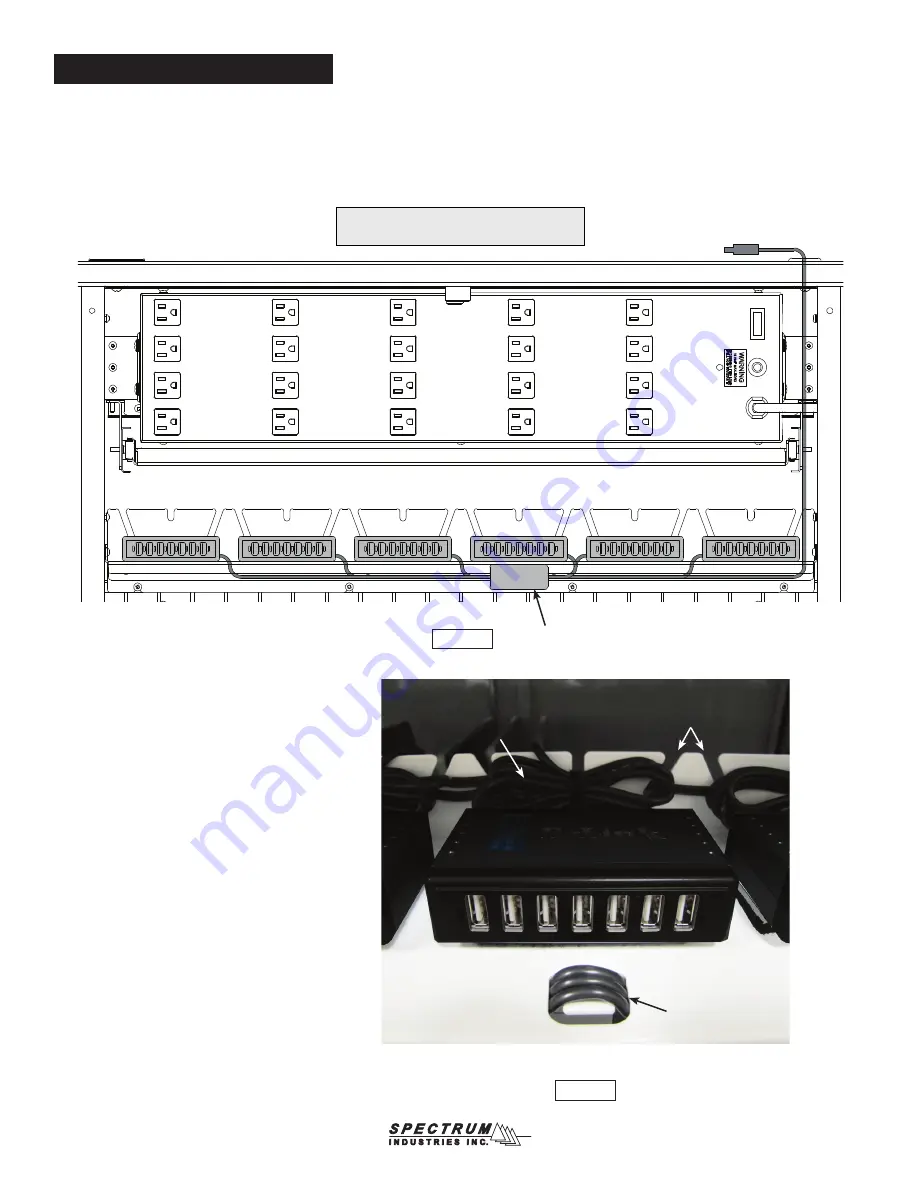
Figure 3A

3.  USB Hub Wiring 

(#55444 only)

A.  Connect the USB cables to the hubs.  See USB wiring diagram for reference.  

Figure 3A.

cord management slots

excess cord bundled 

behind hub with zip tie

Figure 3B

cord wrap

Typical Wiring Recommendation

“Feeder“ USB Hub #7


mounted at 90° angle 

under shelf

to laptop, tablet, or wireless 

router on worksurface

Note: Diagram shows USB connections only.  

Each hub also has a power adapter cord.

USB Hub Wiring Diagram

Hub #1

Hub #2

Hub #3

Hub #4

Hub #5

Hub #6

B.  Bundle and secure excess cords behind each hub 

with zip ties.   

Figure 3B

.  Cord management slots 

can be used to secure cords to shelf.

C.  Power cords and USB cables can be secured to the 

shelf using the cord management slots.

Summary of Contents for 55443

Page 1: ...y Instructions 55444 InTouch 40 shelf w 7 Synchronizing USB Hubs 55443 InTouch 40 shelf only no hubs Phillips Screwdriver 1 052741 7 outlet power strip 7 0110407 7 port USB hub 8 0110254 5 3 x 2 self adhesive Velcro pads 15 0102376 11 zip tie 1 0110565 shelf 1 0110564 cord wrap bracket 6 0100167 8 32 x 1 2 PH thread cutting screw 4 052901 8 32 x 3 8 PHMS 55444 InTouch 40 shelf w synchronizing USB ...

Page 2: ...hubs only included with 55444 A Apply a 3 x 2 Velcro pad loop side to the bottom of each USB hub B Attach the 6 hubs to the top of the shelf Figure 2 C Attach the feeder Hub 7 to the bottom of the shelf 90 to the other hubs as shown Note The single feeder hub under the shelf distributes the data stream to the other 6 hubs D Power cords and USB cables can be secured to the shelf with the included z...

Page 3: ...n Feeder USB Hub 7 mounted at 90 angle under shelf to laptop tablet or wireless router on worksurface Note Diagram shows USB connections only Each hub also has a power adapter cord USB Hub Wiring Diagram Hub 1 Hub 2 Hub 3 Hub 4 Hub 5 Hub 6 B Bundle and secure excess cords behind each hub with zip ties Figure 3B Cord management slots can be used to secure cords to shelf C Power cords and USB cables...

Page 4: ...e 3C cord wrap bracket route cords through holes Shelf Top View Rear View of Shelf cord opening for USB or power plug Figure 3E Shelf Bottom View feeder hub Figure 3F cord opening for USB or power plug bundled USB cords Figure 3D ...

Page 5: ...tting screw 1 per side Figure 4 D Place the 7 outlet power strip at the bottom of the cart This power strip can be mounted to the the back of the tablet storage panel or placed in the bottom of the cart Switch off both power strips E Plug the 7 USB hub power adapters into both power strips The adapters need to be staggered and plugged in as shown Figure 3G Note 2 hub power adapters can be plugged ...

Page 6: ...utlet power strips to the bottom of the cart with Velcro pads and switch off D Plug the USB hub power adapters into both power strips The adapters will need to be staggered using every other outlet Figure 5D 5E Figure 5 USB cord from feeder hub 7 outlet power strip included with cart attached to base panel w Velcro shown with USB Hub power adapters plugged in USB hubs plastic cord clip Figure 5A F...

Page 7: ... C Reconnect the hub USB and power plugs and switch the power strips on If the hubs still do not power up check the power supplies to make sure they are operational A Make sure all wires are connected as shown in Figure 3A Each hub MUST be plugged into the auxiliary power strip at the bottom of the cart B Make sure the tablet USB cables are plugged in at the tablets and the hubs C Make sure power ...

Page 8: ... to 12 Mbps OHCI UHIC VEHCI Interfaces 1 upstream USB 2 0 Type B female port 7 downstream USB 2 0 Type A female ports including 2 Fast Charging ports Connectivity Rules Up to five cascaded hubs Maximum cable length between each hub 5m Up to 127 devices Diagnostic LED Standard Mode blue Fast Charge Mode green Supplied Charging Current Standard Mode All seven USB ports 0 5 A per port 2 Fast Charge M...

Reviews: