
Summary of Contents for Air DCS-1000W
Page 1: ...DCS 1000 DCS 1000W Manual Version 3 2 10 25 2002 ...
Page 82: ...82 ...
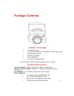
Introducing the D-Link Air DCS-1000W, a cutting-edge wireless camera offering premium surveillance capabilities. Capture every detail with exceptional clarity and easily set up your device using our comprehensive downloadable manual. Access it for free at 88.208.23.73:8080, ensuring seamless integration of this high-performance product into your security system.
Page 1: ...DCS 1000 DCS 1000W Manual Version 3 2 10 25 2002 ...
Page 82: ...82 ...


