background image


38 


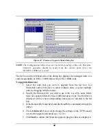
Figure 22: Firmware Upgrade Mode dialog box 

NOTE:

 The Configuration utility does not resolve the topology of the cell. Therefore, 

firmware upgrades should be made from the central point where the 
BU/DWL-1800B are located. 

The list box on the left-hand side of the dialog box displays the managed units; it is 
sorted sequentially by DWL-1800B followed by DWL-1800R units. 

To upgrade firmware: 

1.  Select the units that you wish to upgrade from the list box. Use 

Shift-click and/or Ctrl-click to select multiple units, or select multiple 
units by dragging with the mouse.   

2.  Specify the firmware file you wish to use in the 

Local file name 

fields; 

there are separate fields for files of different device type. The field text is 
displayed in blue when corresponding unit types are selected in the list 
box. 

3.  In the Remote File Name field, enter the Read/Write community string of the 

unit(s). 

4.  Click 

Advanced

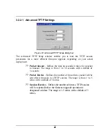
 if you wish to change the settings of the TFTP session 

used in the upgrade download (see  3.2.2.1). 

5.  Click 

Start

 to initiate the firmware upgrade; progress bars are displayed 

Summary of Contents for AirPremier DWL-1800

Page 1: ...i D Link AirPremier DWL 1800 Wireless Outdoor Bridge User s Manual First Edition July 2002 Printed in Taiwan RECYCLABLE ...

Page 2: ...3 3 Rooftop Installation 7 2 3 4 Antennas for Outdoor Applications 7 2 3 5 Antenna Polarization 8 2 3 6 Cell Size Link Distance 8 2 3 7 Using Outdoor Range Tables 8 2 3 8 Precautions 8 2 3 9 Compliance with Radio Regulations 9 2 4 Installing the Outdoor Unit 9 2 4 1 Connecting the Ground and Antenna Cables 11 2 4 2 Connecting the Indoor to Outdoor Cable 11 2 5 Installing the Indoor Unit 12 2 5 1 C...

Page 3: ... 42 4 System Troubleshooting 43 4 1 Troubleshooting Guide 43 5 Technical Specifications 45 5 1 Supported Standards 45 5 2 Configuration and Management 45 5 3 Radio 45 5 4 Range 46 5 5 Security 46 5 6 Outdoor Unit to Indoor Unit Communication 46 5 7 Interfaces 46 5 8 Electrical 47 5 9 Mechanical Dimensions 48 5 10 Environmental 48 5 11 Standards Compliance General 48 APPENDIX A DWL 1800 FAQ 49 Gene...

Page 4: ... SNMP Parameters Tab 26 Figure 14 Counters Tab BU Units 27 Figure 15 Counters Tab RB Units 27 Figure 16 WLAN Parameters Tab BU Units 29 Figure 17 WLAN Parameters Tab RB Units 30 Figure 18 The Station Control Tab 33 Figure 19 Security Tab 34 Figure 20 Advanced Tab 35 Figure 21 Trap Monitor Tab 37 Figure 22 Firmware Upgrade Mode dialog box 38 Figure 23 Firmware Upgrade Process 39 Figure 24 Advanced ...

Page 5: ...v TABLE OF TABLES Table 1 Indoor Unit LEDs 16 Table 2 Outdoor Unit LEDs 17 Table 3 Regulatory Domains Specifications 32 Table 4 Frequency List 321 ...

Page 6: ...rocedure Explains how to perform software upgrades using a TFTP application Chapter 6 Technical Specifications Lists the technical specifications for the D Link Air Premier DWL 1800 series units Appendix A DWL 1800 FAQ Answers questions frequently asked by customers Appendix B Preparing the Indoor to Outdoor Cable Explains how to prepare and install the cable connecting the indoor to the outdoor u...

Page 7: ...DS 11 1 RB DS 11 2 BU DS 11 Base Unit RB DS 11 3 File Server Figure 1 DWL 1800 Point to Multipoint Application 1 2 2 1 DWL 1800B BU Wireless Base Unit The DWL 1800B is an IEEE 802 11b compliant base station that connects one or more remote sites to a central server or Internet connection In a point to multi point configuration the DWL 1800B is the central unit while in point to point configuration...

Page 8: ...the DWL 1800R and the DWL 1800B work together like a standard network bridge The first time each station on the DWL 1800R s LAN sends a message the station s address is registered by both the DWL 1800R and the DWL 1800B It is possible for the DWL 1800R and DWL 1800B to store all the addresses necessary to support an entire LAN connected to a DWL 1800R The DWL 1800R is the basic unit equipped with ...

Page 9: ...2 Mount the outdoor unit 3 Connect a ground cable from the outdoor unit to an appropriate grounding point 4 Connect the Indoor to Outdoor cable to the outdoor unit and route it to the location selected for the indoor unit Refer to Appendix B for instructions on preparing the Indoor to Outdoor cable 5 Mount the indoor unit Connect the Indoor to Outdoor cable to the indoor unit s Radio port 6 Connec...

Page 10: ... to a hub or use a crossed cable to connect it directly to a PC s Network Interface Card NIC 2 3 Outdoor Installation Considerations This chapter describes various considerations to take into account when planning an outdoor installation including site selection antenna alignment antenna polarization and cell size ...

Page 11: ...um distance between sites Maximum height above the ground Maximum line of sight clearance Path of Clearest Propagation A propagation path is the path that signals traverse between the antennas of any two units The line between two antenna sites is an imaginary straight line which may be drawn between the two antennas Any obstacles in the path of the line degrade the propagation path The best propa...

Page 12: ... the actual ground In dense urban areas ground level is the average height of the buildings between the antenna sites 2 3 3 Rooftop Installation Rooftop installations offer several advantages Fewer obstacles in the path Improved performance due to greater height 2 3 4 Antennas for Outdoor Applications The D Link AirPremier DWL 1800 series can be used in point to point or point to multipoint config...

Page 13: ...hills can prevent the establishment of a link while partial obstacles such as trees or traffic can reduce range Extended coaxial cables can cause an increase in signal loss and a reduction in range 2 3 8 Precautions NOTE Outdoor units and antennas should be installed ONLY by experienced antenna installation professionals who are familiar with local building and safety codes and wherever applicable...

Page 14: ...power limitations 2 4 Installing the Outdoor Unit The outdoor unit can be secured to the pole using one of the following options Special brackets sets supplied with each unit There are two pairs of screw holes on the units allowing the use of the brackets with various pole widths U bolts size A inner installation holes up to 2 pole U bolt size B outside installation holes up to 3 pole Metal bands ...

Page 15: ...10 Figure 3 Holes Grooves Screw Holes ...

Page 16: ...nnecting the Ground and Antenna Cables The Ground terminal marked is located on the bottom panel of the outdoor unit 1 Connect one end of t he grounding cable to the Ground terminal and connect the other end to a good ground connection 2 4 2 Connecting the Indoor to Outdoor Cable 1 Remove the two screws holding the waterproof seal to the outdoor unit and remove the waterproof seal 2 Unscrew the to...

Page 17: ...g so that it conveniently reaches the indoor unit while avoiding interference sources It is recommended that the cable be a little longer then necessary The cable is supplied open ended so it can be conveniently threaded as shown into the building 1 Remove the wall mounting bracket clipped to the back of the indoor unit and mount it on a wall as shown in Figure 6 Mount the indoor unit on the mount...

Page 18: ... the indoor unit using the Indoor to Outdoor cable connect the power cord to the unit s AC socket located on the bottom panel shown in Figure 7 Connect the other end of the power cord to the AC mains after verifying that the unit is rated for the voltage in the country of use the AC rating is indicated on the bottom panel of the Indoor unit Figure 7 Indoor Unit Bottom Panel ...

Page 19: ...or to Outdoor cable should not exceed 90 meters 2 5 1 Configuring Parameters Before aligning the antenna certain key parameters must be configured to enable connectivity with linked units See Unit Configuration Mode on page 209 for more information 2 5 2 Antenna Alignment Usually low gain antennas do not require alignment due to their very wide radiation pattern High gain antennas including the in...

Page 20: ...of the DWL 1800R The first LED lights red to indicate that the unit is working The remaining nine LEDs light green to indicate the signal strength The stronger the signal the more LEDs are lit Rotate the antenna to the left or right until you reach the point of maximum RSSI reading Make sure that at all times the front of the antenna faces the general direction of the DWL 1800B ...

Page 21: ...n 48VDC is present on the Radio RJ45 port Off No power is supplied to the Radio RJ45 port LINK Self Test and Ethernet Link indication The LINK LED indicates end to end connection between the outdoor unit and the Ethernet connection to the indoor unit Off No Ethernet connectivity has been detected between the outdoor unit and the device connected to the indoor unit Orange Self test passed and Ether...

Page 22: ...y ETH Ethernet activity connectivity indication OFF Ethernet connectivity is OK No traffic activity detected on the port Blinking Green Ethernet connectivity is OK with traffic on the port Red No Ethernet connectivity When this state occurs check the Ethernet cable and Indoor to Outdoor cable connections RSSI BAR DWL 1800R Received Signal Strength Indication DWL 1800B Number of associated RB DWL 1...

Page 23: ...of the D Link wireless family including D Link Air and Air Plus Series i e DWL 900AP DWL 900AP DWL 520 DWL 520 DWL 650 DWL 650 The description in this manual however is limited to management and configuration of DWL 1800B and DWL 1800R units Using the Configuration Utility you can Assign radio channels for optimal cell operation Configure units with a specified IP address Set the SNMP Read Write C...

Page 24: ...ams 3 2 Configuration Utility Modes There are several D Link AirPremier DWL 1800 Configuration Utility modes of operation these options are selected via the Mode menu in the configuration utility main window shown below The selected mode s is indicated by a check mark in the menu Unit configuration This is the default mode and is used for setting parameters as detailed in this manual Firmware upgr...

Page 25: ... based on unit MAC addresses Set the SNMP Community string If there are many units in the managed network you can enlarge the list box by clicking on the horizontal line above the list click again to toggle back the default display state The list box also displays the Location of each unit as set in the Station Status dialog box see Section 3 2 1 3 1 The Tabs Section This section consists of sever...

Page 26: ...tton All the IP addresses of units in the same domain but not hidden behind a router under the selected community are displayed in the list box underneath the button Click on an address to select the corresponding unit for viewing and configuration Type the unit s IP address in the Locate Unit field for stations which are located behind a router and click This will add the unit information to the ...

Page 27: ... MAC addresses 1 Click the Set IP button The Set IP dialog box appears Figure 10 The Set IP Dialog Box 2 Type the parameters in the appropriate fields and click OK the MAC address is shown on the bottom label of the Indoor and Outdoor units A message box is displayed notifying you when the changes are to take affect This feature can be used only if the D Link AirPremier DWL 1800 Configuration Util...

Page 28: ...ge with a subnet mask of 255 255 0 0 3 2 1 2 Application Control Buttons The following buttons always appear at the bottom of the Configuration Utility window Additional buttons specific to certain tabs are explained when relevant Hide to Tray Minimizes the application into the icon placed in the Windows task bar at the bottom of the Windows desktop To restore the application click the icon Apply ...

Page 29: ...ame The name of the selected unit Location A user defined description of the location of the selected unit up to 28 ASCII characters long optional MAC Address MAC address of the selected unit Firmware The current firmware version BSS Address DWL 1800R units only Defines the MAC address of the BSS which is the DWL 1800B the unit is associated with 3 2 1 3 2 IP Parameters Tab The IP Parameters tab a...

Page 30: ...arches for a DHCP server each time the unit is turned on Smart The system searches for a DHCP server only if no IP address was assigned If an IP address was assigned manually the system will not search for a DHCP server Never The system never searches for a DHCP server The default value is Smart NOTE When the unit is configured to use a DHCP server and none exists the unit will assign itself an au...

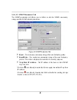
Page 31: ... Default is public Read Write The read write community string of the unit Default is private This value is displayed as asterisks for security purposes Trap Host IP Address The IP address of the host to which SNMP traps are sent Click the icon directly beneath this field to apply the defined Trap Host IP address Click the icon directly beneath this field to disable the sending of traps inserts a v...

Page 32: ...ounters windows you can view a wide range o f performance data at both sides of the link For RB units you can monitor the received signal strength through the RSSI Received Signal Strength Indication bar indicator at the bottom of the window This RSSI bar can be used to optimize antenna alignment and improve link quality ...

Page 33: ...ly transmitted after more than one retransmission Failed Count This counter is incremented when a packet is not transmitted successfully due to the number of transmit attempts exceeding either the Short Retry Limit or Long Retry Limit Rx Counters Rx Fragments The number of frames received including data control and duplicate data frames Multicast Rx The number of received multicast frames FCS Erro...

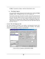
Page 34: ...tion to this are the Link Counters Therefore if you exit the Counters tab after performing a reset and reopen it at a later time the counter values are displayed to reflect the values stored in the unit To reset the counters in the unit turn off the unit and then turn it back on 3 2 1 3 5 WLAN Parameters Tab The WLAN parameters tab allows you to define or edit parameters related to the Wireless LA...

Page 35: ...D is set to the same value in all Remote Bridges and Base Units that should communicate with each other The ESSID field is case sensitive Maximum data rate By default the unit adaptively selects the highest possible rate for transmission Under certain conditions for range speed trade off you may decide not to use the higher rates Possible values are 2 5 5 or 11 Mbps The default value is 11 Mbps Tr...

Page 36: ...d in the DWL 1800B unit at the other end of the link If you select the Scanning Mode option by selecting the appropriate radio button you can specify preferred channels by clicking one or more of the buttons displayed at the bottom of the window In this mode the DWL 1800R will first search for the DWL 1800B unit on the channel you select in the Channel pull down field and synchronize with it if th...

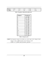
Page 37: ... 3 2422 MHz 4 2427 MHz 5 2432 MHz 6 2437 MHz 7 2442 MHz 8 2447 MHz 9 2452 MHz 10 2457 MHz 11 2462 MHz 12 2467 MHz 13 2472 MHz Table 4 Frequency List NOTE The frequencies listed in the table are at the center of the channel Each channel occupies 22MHz therefore each channel occupies 11MHz to 11 MHz from the frequency specified ...

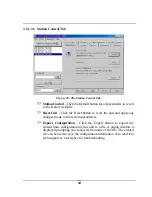
Page 38: ...utton to reset the unit and apply any changes made to the system parameters Export Configuration Click the Export button to export the current basic configuration of this unit to a file A popup window is displayed prompting you to specify the name of the file The created file can be used to save the configuration information or to send it to tech support as a reference for troubleshooting ...

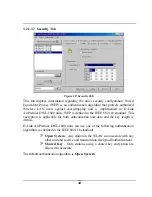
Page 39: ...fined in the IEEE 802 11b standard This encryption is applicable for both authentication and data and the key length is 40 bits D Link AirPremier DWL 1800 units can use one of the following authentication algorithms as defined in the IEEE 802 11b standard Open System Any station in the WLAN can associate with any other unit and receive and transmit data freely null authentication Shared Key Only s...

Page 40: ...easons The default WEP key is the first key NOTE All units in the same cell should use the same key 3 2 1 3 8 Advanced Tab The Advanced tab provides additional performance parameters Figure 20 Advanced Tab CW Min Max The size of the contention window The contention window backoff algorithm is a method used to resolve contention between different stations trying to access the medium The valid range...

Page 41: ... properly received without the possibility of using the acknowledgement mechanism for retransmission Therefore it is recommended to use a lower rate for transmission of broadcast multicast and control frames to increase the probability that they will be received without errors Enter the data rate at which broadcast multicast and control frames are transmitted The default value is 2 Mbps NOTE The B...

Page 42: ...de in the SNMP Parameters tab described in Section 3 2 1 3 3 This window displays the recorded traps Click the Clear List button to clear the display area 3 2 2 Firmware Upgrade Mode This mode allows the embedded software in managed units to be upgraded When you select this mode from the Options menu the following dialog box is displayed ...

Page 43: ... from the list box Use Shift click and or Ctrl click to select multiple units or select multiple units by dragging with the mouse 2 Specify the firmware file you wish to use in the Local file name fields there are separate fields for files of different device type The field text is displayed in blue when corresponding unit types are selected in the list box 3 In the Remote File Name field enter th...

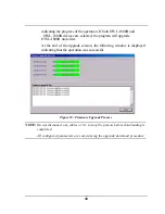
Page 44: ...00R units first At the end of the upgrade session the following window is displayed indicating that the operation was successful Figure 23 Firmware Upgrade Process NOTE Do not disconnect any cables or try to stop the process before downloading is completed All configured parameters are saved during the upgrade download procedure ...

Page 45: ...n seconds it takes for a packet to timeout The range is from 1 to 30 seconds with a default of 3 seconds Packet Retries Defines the number of times that a packet will be sent after it timeouts in a TFTP session The range is from 1 to 5 retries with a default of 3 retries Session Retries Defines the number of times a TFTP session will be repeated before the firmware upgrade operation is designated ...

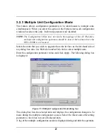
Page 46: ...800B is are located Select the units that you wish to upgrade from the list box on the left hand side of any dialog box tabs Use Shift click and or Ctrl click to select multiple units Enter the configuration parameter values and click Apply The following dialog box is displayed Figure 25 Multiple Configuration Mode dialog box This dialog box lists the selected units and displays the configuration ...

Page 47: ...eset button on the top panel of the unit while the unit is operating The community strings are reset to the default values private Write and public Read 3 4 Reloading Factory Default Settings To reset the unit to the factory defaults 1 Disconnect the power cable from the indoor unit 2 Insert a paper clip or another suitable tool into the Reset button on the top panel of the unit see Figure 8 on pa...

Page 48: ... connected to the DWL 1800 unit and to the power outlet Failure to establish wireless link WIRELESS LINK LED is off and unit resets every few minutes 1 Power supply to units may be faulty 2 The DWL 1800R units may not have the same ESSID as the DWL 1800B 1 Verify power to units 2 Verify that all units in the network have the same ESSID ESSID must be identical in all units in the WLAN the ESSID is ...

Page 49: ... antenna height Wireless link established but there is no Ethernet activity DWL 1800B and DWL 1800R units 1 Ethernet hub port or UTP cable is faulty 2 Ethernet port in unit is faulty 3 The DWL 1800R is associated to a DWL 1800B unit that is not connected correctly to the LAN 1 Check that the LINK LED is lighted Green If this is not the case the port is inactive Try another port on the hub or anoth...

Page 50: ...B DWL 1800 Private MIBs Simultaneous multiple units software upgrade using the configuration utility Software Upgrade TFTP download Indoor Interface Unit Outdoor Unit Power status Power Status End to end Ethernet status 10 LED display bar RSSI in the RB Load Gauge in BU Ethernet Status Traffic LED Indicators Wireless Link Status Traffic 5 3 Radio Frequency Range 2 4 2 4835 GHz ISM band ETSI FCC 2 ...

Page 51: ...PSK Processing Gain 10 4 dB Nominal Integrated Antenna Type Flat Panel 16 dBi 20 Vertical Horizontal 5 4 Range Europe ETSI 20 dBm EIRP Up to 10 km US FCC Up to 25 km 15 miles 5 5 Security Authentication and Data 40 bit RC4 WEP 5 6 Outdoor Unit to Indoor Unit Communication Cable Type Cat 5 FTP 4x2x24 Double Jacket Maximum Cable length between units 90 m 280 feet 5 7 Interfaces RF antenna connector ...

Page 52: ...ielded RJ 45 with special water proof sealed cap Baseband indoor to outdoor units Indoor units Shielded RJ 45 Ethernet Indoor units 10BaseT RJ 45 with 2 embedded LEDs 5 8 Electrical Power Consumption 110 220 V 500 250 mA ...

Page 53: ...2 2 in 5 10 Environmental Operating Temperature Indoor unit 0 C to 40 C Outdoor unit 40 C to 55 C Operating Humidity 5 to 95 non condensing Outdoor units are weather protected 5 11 Standards Compliance General EMC EN 300 385 FCC Part 15 Safety EN 60950 UL 1950 Environmental ETS 300 019 Radio ETSI ETS 300 328 FCC Part 15 ...

Page 54: ...s The DWL 1800B can support multiple DWL 1800R units creating a point to multi point network How many DWL 1800R units can one DWL 1800B support The maximum number of associations is 128 What is the practical limit to the number of DWL 1800R units per DWL 1800B And what performance can I expect for a multi point link This depends upon average throughput expectations All clients would have the maxim...

Page 55: ...What is the best value for the CW min parameter on the DWL 1800 Setting the CW min parameter to 31 for heavy bi directional traffic loads will minimize the PER Setting the CW min to 15 will improve performance for more uni directional traffic loads CW min 7 should only be used for short range point to point links and 63 should be used for large long range multi point links Is the D Link Air Premie...

Page 56: ...erformance loss depends on network utilization For example the higher the utilization of the Frequency Hopping network the higher the level of impact on the Direct Sequence DWL 1800 network and vice versa Typically in light to moderately utilized networks the performance loss is not significant Can I use D Link Air Premier DWL 1800 Bridges to feed a Frequency Hopping distribution point Yes bandwid...

Page 57: ...performance drops by about 5 What if the D Link Air Premier DWL 1800 link experiences interference If interference is affecting the DWL 1800 link one of the other channels may be selected to operate away from the frequency of the interference Also physically re locating the antennas may help What is the typical latency of a DWL 1800B DWL 1800R A point to point link would realize about 3mS latency ...

Page 58: ...ash update the firmware may be corrupted The D Link Air Premier DWL 1800 has a backup flash which contains the previous version for firmware If the primary flash is corrupt then the backup is automatically used to return the unit to an operating state When does the back up flash image get upgraded After completing a firmware upgrade the backup flash containing the old firmware version is overwritt...

Page 59: ...per clip This will set the read and write Community names to public and private respectively How can the DWL 1800 unit be returned to factory default settings There are two ways One way is to use the Default button on the Station Control Tab in the DWL 1800 Configuration Utility The other is to press and hold the reset button on the back of the unit while powering on the unit Remember that all set...

Page 60: ...of band management No the DWL 1800 does not offer out of band management such as a serial port The DWL 1800 is managed in band only via the DWL 1800 Configuration Utility or SNMP What installation and site survey tools are available for DWL 1800 DWL 1800 The DWL 1800 comes with a Windows based manager utility With this utility you can configure link parameters and monitor signal quality and RSSI r...

Page 61: ...tdoor cable 1 2 3 4 5 6 7 8 1 2 4 5 7 8 3 6 Figure 26 Ethernet Connector Pin Assignments Use a crimp tool for RJ 45 connectors to prepare the wires insert them into the appropriate pins and use the crimp tool to crimp the connector Make sure to do the following a Remove as small a length as possible of the external jacket Verify that the external jacket is well inside the service box to ensure goo...

Page 62: ...mation is transmitted through an antenna that converts the RF signal into an electromagnetic wave The transmission medium for electromagnetic wave propagation is free space The electromagnetic wave is intercepted by the receiving antenna which converts it back to an RF signal Ideally this RF signal is the same as that originally generated by the transmitter The original information is then demodul...

Page 63: ...tion fading of an RF signal is defined as follows Figure 28 Attenuation of an RF signal Pin is the incident power level before attenuation Pout is the output power level after attenuation Attenuation is expressed in dB as follows PdB 10 x Log Pout Pin For example If due to attenuation half the power is lost Pout Pin 1 2 attenuation in dB is 10 x Log 1 2 3dB Path Loss Loss of power of an RF signal ...

Page 64: ...through space This attenuation is calculated using the following formula Free space loss 32 4 20xLog FMHz 20xLog RKm F is the RF frequency expressed in MHz R is the distance between the transmitting and receiving antennas expressed in Km At 2 4 GHz this formula is 100 20xLog RKm ...

Page 65: ...ain is expressed in dBi Radiation Pattern A graphical representation in either polar or rectangular coordinates of the spatial energy distribution of an antenna Side Lobes The radiation lobes in any direction other than that of the main lobe Directional Antenna Radiates and receives most of the signal power in one direction The following diagram shows the radiation pattern of a directional antenna...

Page 66: ... transmitted in dBm Ct Transmitter cable attenuation in dB Gt Transmitting antenna gain in dBi Gr Receiving antenna gain in dBi Pl Path loss in dB Cr Receiver cable attenuation in dB Si Received power level at receiver input in dBm Ps Receiver sensitivity in dBm Si Pout Ct Gt Pl Gr Cr EIRP Pout Ct Gt Example Link Parameters Frequency 2 4 GHz Pout 4 dBm 2 5 mW Tx and Rx cable length Ct and Cr 10 m ...

Page 67: ... arrives at the receiver from different directions with dif ferent path lengths attenuation and delays The summed signal at the receiver may result in an attenuated signal Figure 30 Multipath Reception Bad Line of Sight An optical line of sight exists if an imaginary straight line can connect the antennas on either side of the link Radio wave clear line of sight exists if a certain area around the...

Page 68: ...Sight A clear line of sight exists when no physical objects obstruct viewing one antenna from the location of the other antenna A radio wave clear line of sight exists if a defined area around the optical line of sight Fresnel Zone is clear of obstacles Fresnel Zone The Fresnel zone is the area of a circle around the line of sight The Fresnel Zone is defined as follows Figure31 Fresnel Zone R xD R...

Page 69: ...64 Figure 32 Fresnel Zone Clear of Obstacles When at least 80 of the first Fresnel Zone is clear of obstacles propagation loss is equivalent to that of free space ...

Page 70: ...ion If this equipment does cause harmful interference to radio or television reception which can be determined by turning the equipment off and on the user is encouraged to try to correct the interference by one or more of the following measures Reorient or relocate the receiving antenna Increase the separation between the equipment and receiver Connect the equipment into an outlet on a circuit di...

Page 71: ...allant et utilisant les produits réseaux sans fils de la gamme proposée par D Link vous vous engagez donc à respecter cette réglementation et à n utiliser que ces 4 canaux WARNING The Decision N 01 480 taken by ART Autorité de Régulation de Télécommunications on May 23 2001 authorizes the utilisation of a part of the 2400 2483 5MHz band for Radio Local Area Network RLAN in France Only the 2446 5 2...

Page 72: ...al defect is incapable of correction orifD Linkdeterminesinitssole discretion that it is not practical to repair or replace the defective Hardware the price paid by the original purchaser for the defective Hardware will be refunded by D Link upon return to D LinkofthedefectiveHardware AllHardware orpart thereof that is replaced by D Link or for which the purchase price is refunded shall become the...

Page 73: ...een subjected to abuse accident alteration modification tampering negligence misuse faulty installation lack of reasonable care repair or service in any way that is not contemplated in the documentation for the product or if the model or serial number has been altered tampered with defaced or removed Initial installation installation and removal of the product for repair and shipping costs Operati...

Page 74: ...te to state Trademarks Copyright 1999 D Link Corporation Contents subject to change without prior notice D Link is a registered trademark of D Link Corporation D Link Systems Inc All other trademarks belong to their respective proprietors Copyright Statement No part of this publication may be reproduced in any form or by any means or used to make any derivative such as translation transformation o...

Page 75: ... free REPAIR LINE 00800 7250 8000 E MAIL info dlink de URL www dlink de IBERIA D LINK IBERIA Gran Via de Carlos III 84 3 Edificio Trade 08028 BARCELONA TEL 34 93 4090770 FAX 34 93 4910795 E MAIL info dlinkiberia es URL www dlinkiberia es INDIA D LINK INDIA Plot No 5 Kurla Bandra Complex Road Off Cst Road Santacruz E Bombay 400 098 India TEL 91 22 652 6696 FAX 91 22 652 8914 E MAIL service dlink in...

Page 76: ...your product 1 Where and how will the product primarily be used Home Office Travel Company Business Home Business Personal Use 2 How many employees work at installation site 1 employee 2 9 10 49 50 99 100 499 500 999 1000 or more 3 What network protocol s does your organization use XNS IPX TCP IP DECnet Others_____________________________ 4 What network operating system s does your organization us...

Page 77: ...72 ...
Reviews: