background image

10

D-Link DCS-340 User Manual

Section 3 - Configuration

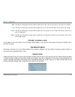
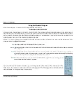
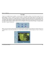
This button will take a snapshot of the selected video channel and then save the picture as a bitmap 
file to the hard disk. You can set the directory for storing these bitmap files at the “Configuration menu > 
Global Settings screen”. Please refer to the section titled “Global Settings” for more details.

Click on the printer icon to print the current image to your default printer.

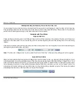
You can drag and drop the video channel to the Trash can to close the video connection with the 
DCS-3420.

Status Bar

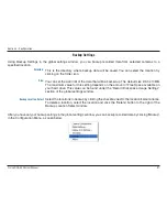
The status bar, shown below, displays important information about the IP surveillance program such as: Local Time, 
Current Login User, Login Time, Software Name, and Software Version.

Scheduling

Snapshot:

Printer:

Trash can:

Summary of Contents for DCS-3420

Page 1: ......

Page 2: ...s XP 23 Testing the DCS 3420 28 Viewing Your DCS 3420 29 Using the DCS 3420 with an Internet Browser 30 Home 31 Connection Type 32 Configuration 33 Advanced 33 Network 33 Wireless 35 Mail FTP 37 DDNS UPnP 39 Video 40 Audio 43 Image Setting 44 Motion Detection 45 Tools 46 Admin 46 System 47 Applications 48 Default 50 Status 51 Device Info 51 Log 52 Help 53 Record Snapshots to your FTP server 54 I O...

Page 3: ...ty 121 What is WEP 121 What is WPA 122 Setting Security 123 Using Configuring the DCS 3420 124 Router Set Up and Installation 128 Troubleshooting 131 Wireless Basics 134 Networking Basics 139 Check your IP address 139 Statically Assign an IP address 140 Technical Specifications 141 Contacting Technical Support 143 Warranty 144 Registration 149 ...

Page 4: ... and void the warranty for this product If any of the above items are missing please contact your reseller System Requirements Windows 2000 or XP At least 256MB of memory 512MB recommended An available Ethernet connection Internet Explorer 6 x or higher Internet Web Browser VGA card resolution 800x600 or above CPU 1 7GHz or above processor 2 8GHz plus processor with 512MB memory and a 32MB video c...

Page 5: ...the DCS 3420 s 4x digital zoom2 feature The DCS 3420 gives you the ability to monitor video and audio in your home office using an Internet browser from any where in the world Simple installation procedures along with the built in Web based interface offers easy integration to your network environments Note Use of audio or video equipment for recording the image or voice of a person without their ...

Page 6: ...lt in BNC Bayonet Neil Concelman connector is used for professional video connections It benefits users who integrate digital IP camera into traditional system CCTV for both analog and digital video streaming purpose Powerful Surveillance and Remote Monitoring Utility The powerful IP surveillance software assigns an administrator with a pre defined user ID and password who can modify the Internet ...

Page 7: ...e camera to provide audio for 2 way communication Ethernet Cable Connector The Internet Camera s back panel features an RJ 45 connector for connections to 10Base T Ethernet cabling or 100Base TX Fast Ethernet cabling This network port supports the NWay protocol allowing the Internet Camera to automatically detect or negotiate the transmission speed of the network Microphone Connector The DCS 3420 ...

Page 8: ... Reset Button Reset will be initiated when the reset button is pressed once and held until the Power LED flashes through its cycle twice BNC The BNC connector is used for professional video connections It benefits users who integrate digital IP camera into traditional system CCTV for both analog and digital video streaming purpose Power LED The power LED is positioned on the back of the camera len...

Page 9: ...ck of the DCS 3420 Attach the external power supply to the DC power input connector located on the Internet Camera s back panel labeled 12VDC and connect it to your wall outlet Note When you have a proper connection the LED will turn from red to green The light may cycle on and off and your computer may show an intermittent loss of connectivity this is normal until you have configured your Interne...

Page 10: ...all screw head that can be attached to the Internet Camera bottom socket cavity Attach the camera stand to the Internet Camera and station it for your application There are holes located in the base of the camera stand allowing the Internet Camera to be mounted to the ceiling or any wall securely Socket for camera stand ...

Page 11: ...t is 1 5 feet thick 5 meters at a 45 degree angle appears to be almost 3 feet 1 meter thick At a 2 degree angle it looks over 42 feet 14 meters thick Position devices so that the signal will travel straight through a wall or ceiling instead of at an angle for better reception 3 Building Materials make a difference A solid metal door or aluminum studs may have a negative effect on range Try to posi...

Page 12: ...are shown in Windows XP The steps and screens are similar for the other Windows operating systems If the CD Autorun function does not automatically start on your computer click Windows Start Run In the Run command box type D DCS3420 exe where D represents the drive letter of your CD ROM If it does start proceed to the next screen Software Installation Click Installation Wizard ...

Page 13: ...13 D Link DCS 3420 User Manual Section 2 Installation Please wait while the InstallShield Wizard prepares to install Click Next ...

Page 14: ...ll the driver in the following folder To install the driver into a different folder click Browse and select another folder Select the Program folder that Setup will add program icons to You may type a new folder name or select one from the existing folders list Click Next Click Next ...

Page 15: ...15 D Link DCS 3420 User Manual Section 2 Installation Please wait while the Installation Wizard is installed Installation is now complete Click Finish ...

Page 16: ...sktop The opening Installation Wizard screen will appear and show a MAC address of the DCS 3420 and an IP Address If you have a DHCP server on your network there will be a valid IP Address displayed here indicated by a Yes under the assigned column A DHCP server is a device that supplies IP Addresses to its clients that are on the same network ...

Page 17: ...ion Wizard The following options are available on the Installation Wizard screen by clicking on the corresponding tab Configuration This section will show you how to configure your new D Link wireless internet camera using the D Link Installation Wizard Click Setup ...

Page 18: ... DCS 3420 User Manual Section 3 Configuration On the initial Setup Screen you can configure System and Date Time settings for each camera Click Next to configure Network settings for the camera Click Next Setup ...

Page 19: ...Settings for the camera by entering the IP address Subnet mask Default router IP Primary DNS and Secondary DNS The option to reset IP address at next boot is automatically selected If you would like to keep your IP address settings make sure to uncheck this box Click Next Network Settings ...

Page 20: ...he SSID and selecting the Wireless Mode Channel TX Rate and Preamble Note Check the Data Encryption box to enable data encryption and configure the settings These settings are explained and can also be configured on the Advanced Network screen page 33 when configuring the camera via a Web Browser Click Next Wireless Network Settings ...

Page 21: ...21 D Link DCS 3420 User Manual Section 3 Configuration Click Apply to save the configured settings Users can click Previous to modify changes Click Apply ...

Page 22: ...Section 3 Configuration The upgrade window allows users to upload the firmware If the firmware is older than the current one on the camera a screen shot will appear indicating this prompting the user to confirm the uploading Upgrade ...

Page 23: ...ating system is UPnP enabled the device will be easier to configure If you do not want to use the UPnP functionality it can be disabled by unchecking the Enabled UPnP checkbox in the Advanced Network page see page 33 Use the following steps to enable UPnP settings only if you are running Windows XP If you are running Windows 98 2000 UPnP is not available Go to Start Settings Click Control Panel En...

Page 24: ...4 D Link DCS 3420 User Manual Section 3 Configuration The following screen will appear Select Networking Services Select Universal Plug and Play Click Details Click Add Remove Windows Components Click OK ...

Page 25: ...25 D Link DCS 3420 User Manual Section 3 Configuration Please wait while Setup configures the components Click Next Click Finish ...

Page 26: ...tion To view your DCS 3420 Internet Camera in an Internet browser go to your Desktop and click My Network Places The last three digits 120 represent the fourth octet of your Internet Camera s IP address in this example 198 168 0 120 Click DCS 3420 120 ...

Page 27: ...e DCS 3420 120 icon your Internet browser will automatically be opened to the IP Address of the DCS 3420 in this example it is http 192 168 0 120 Your DCS 3420 may have a different IP Address Note Screen shots are taken in Windows XP similar screens will appear in Windows 2000 ...

Page 28: ... your computer speakers from the DCS 3420 If you are having problems please consult the Troubleshooting section of this manual page 131 Open your Internet browser and type in the IP address of the DCS 3420 In this example the address is http 192 168 0 120 your DCS 3420 may have a different IP address based on what you used in the Installation Wizard program Testing the DCS 3420 ...

Page 29: ...ing the default Web server port 80 To access from a computer on your local home network simply enter the local IP Address of the Camera followed by a colon and the port number e g http 192 168 0 120 83 Viewing Your DCS 3420 If you are following this manual in the order it is presented you should now have an operating DCS 3420 Internet Camera configured with the Installer program You also have inst...

Page 30: ...your Internet Camera http 192 168 0 120 In the example this address is 192 168 0 120 Your address may differ If a window appears asking to install a Verisign certificate for authentication ClickYes This allows the proprietary MPEG4 video stream to be recognized by Internet Explorer Using the DCS 3420 with an Internet Browser ...

Page 31: ...onfiguration menu where you can configure camera settings under the Advanced Tools and Status tabs Push to enable the speaker You can set the speaker button operation to either Push or Toggle on the Connection Type screen Click to increase or decrease speaker volume Click to mute the speaker Click to increase or decrease microphone volume Click to mute the camera s microphone Push Toggle Speaker V...

Page 32: ...n The chosen protocol will be saved in the user s PC and used for the next connection If the network environment is changed or users want to let the Web browser automatically detect the protocol select UDP manually and click Save to change the setting and return Home to reconnect with the new setting Options UDP Protocol Allows for more real time audio and video streams However packets may be drop...

Page 33: ...ame server that translates names to IP addresses Secondary domain name server to backup the primary one Point to Point Protocol over Ethernet Select this option if the camera is directly connected to the Internet through a DSL modem and the ISP Internet Service Provider requires you to use PPPoE for the Internet connection Input the authentication information from your ISP into these fields Note T...

Page 34: ...n IP address of 192 168 0 120 from 80 to 8080 users must type http 192 1 68 0 120 8080 in the web browser bar to bring up the web interface Can be set to a port other than the default port 5002 A corresponding port must be opened on your firewall Can be set to a port other than the default port 5003 A corresponding port must be opened on your firewall UDP audio port UDP video port ...

Page 35: ...nnecting directly to a computer equipped with a wireless adapter in a peer to peer environment The default wireless channel setting is channel 6 Select the channel that is the same as the otherwireless devices on your network Select the transmission rate on the network Auto is the default setting Select Long or Short Preamble The Preamble defines the length of the CRC block CyclicRedundancy Check ...

Page 36: ... allows the camera to connect to other devices by using WPA PSK encryption Pre shared key must be 8 63 characters or 64 hex characters Choose one of the following authorization modes Open Autenication Communicates the key across the network Shared Authentication Allows communication only with other devices with identical WEP settings Select the key length either 64 or 128 bits Select an ASCII or h...

Page 37: ...ss of recipients for snapshots or a system log file The domain name or IP address of a secondary mail server used only if the primary mail server is unreachable The user name for the second SMTP server The password used to log into the second e mail account The password will appear as dots instead of entered characters The e mail address of recipients for the secondary server SMTP mail server 1 Ma...

Page 38: ...ly the port number of FTP server is 21 It depends on the FTP server s setup The account name to access the FTP server The password that was setup with the account to access the FTP server The directory that the images will be uploaded into For example pub images Allows access to an external FTP sever if your camera is behind a router protected by a firewall The 2nd FTP server serves as a backup FT...

Page 39: ...matically update your DDNS server every time it receives a different IP address Check to enable the DDNS function Select your Dynamic DNS provider from the drop down menu Enter the host name of the DDNS server Enter your username or e mail used to connect to the DDNS server DDNS DDNS UPnP The password that was setup with the account to access the FTP server The directory that the images will be up...

Page 40: ...selecting the Enable UPnP check box Password Key UPnP Video Selecttheoptionforcolorormonochrome video display Three options exist for the video display 176 x 120 352 x 240 and 704 x 480 In 704x480 mode the frame rate will be reduced to 10fps and increased to 30fps automatically when it is switched back to a lower image size Limits the maximum refresh frame rate The frame rate is used with the Vide...

Page 41: ...ing will utilize more bandwidth to send the maximum frames when images change drastically Vertically rotate the video Horizontally rotate the video Check both flip and mirror if the DCS 3420 is to be installed upside down If the camera works in a multi user environment the user can enable this option to conserve bandwidth by reducing video capture rate Select this option to display the current dat...

Page 42: ... your network bandwidth is below 384 Kbps you should adjust the bit rate according to your bandwidth and experiment to allow for the best frame rate that can be achieved The faster frame rate in a slow network will blur the images You may also try to choose 320x240 in size option for better images or 640x480 for larger image size Because the network has burst constraints and everyone s environment...

Page 43: ... the server The User can only listen from the server The audio is disabled in both directions If the Network Camera works in a low bandwidth network environment the User can check this option to improve audio quality by sacrificing some real time synchronization There are three bit rates for audio 32Kbps and 24Kbps are suitable for both music and speech and 8Kbps is suitable for speech only Transm...

Page 44: ...r For each video compensation you can set from among eleven levels ranged from 5 to 5 The default setting is zero for each adjustment You may use the Preview and Restore button to fine tune the image Press the Save button to store the image settings or press the Restore button to recall the original settings If settings are changed without saving they will be effective until the next system start ...

Page 45: ... the image window Up to 3 motion detection windows can be added Saves the new windows settings Enable motion detection Motion Detection Window name Sensitivity Percentage New Save A green bar means the image variation is under the monitoring level and no motion detection alert is triggered A red bar means the image variation is over the monitoring level and a motion detected alert is triggered Whe...

Page 46: ...s by default This allows the ability to access the DCS 3420 including the Configuration by anyone as long as the IP address is known It is recommended that you enter a password to restrict others from accessing your camera Type a password in the Admin Password field to enable protection and then confirm the password in Confirm Password field This password is used to identify the administrator You ...

Page 47: ...CS 3420 An internal real time clock maintains the date and time even when the power is off Synchronizes the date and time of your camera with your computer Adjust the date and time according to what is entered by the administrator Synchronize with the NTP server over the Internet whenever the DCS 3420 starts up The IP address or domain name of the timeserver Leaving the text box blank will let the...

Page 48: ...king snapshots Sets the time to stop taking snapshots Sets the camera to take snapshots all the time except for the times scheduled The camera will send snapshots at the specified intervals to the external server Sets the time delay between triggered events Snapshots begin at Snapshot stop at All the time except for the above schedule Snapshot Interval Delay second s before detecting next event ...

Page 49: ...ernal device at the digital output back to the original state The camera will send snapshots to the external server FTP Email continuously based on the snapshot interval These settings will correspond with the Weekly Schedule Sun Mon that is specified in Applications settings Any upload action specified in the options above will use the method chosen here The captured snapshot named video jpg will...

Page 50: ...ion Default Click Apply on this screen to restore the factory default settings After confirmation the system will restart and require the Installation Wizard software program to locate the IP address of the DCS 3420 For hard reset please refer to page 7 ...

Page 51: ...51 D Link DCS 3420 User Manual Section 3 Configuration Status Device Info ...

Page 52: ...52 D Link DCS 3420 User Manual Section 3 Configuration Log The content of the log file reveals useful information about the current configuration and connection logged after the DCS 3420 starts up ...

Page 53: ...53 D Link DCS 3420 User Manual Section 3 Configuration Help The help page provides detailed information of the camera s web interface ...

Page 54: ...on detection to monitor any abnormal movement and then record the snapshots to a FTP server Record Snapshots to your FTP server In this window follow the steps below to ensure that motion detection is correctly enabled 1 Check Enable motion detection 2 Click on New to have a new window to monitor video 3 Enter in a window name 4 Tune the Sensitivity and Percentage according to the local environmen...

Page 55: ...main name or IP address of your internal external FTP server such as ftp dlink com or ftp 192 168 0 123 The server name and IP address will vary depending on the user The following user settings must be correctly configured for remote access The port of the FTP server The default is 21 for an external FTP site Specify the user name to access the external FTP server e g John Smith Specify the passw...

Page 56: ...he information for the first FTP server The port of the FTP server The default is 21 for an external FTP site Specify the user name to access your backup FTP server Specify the user password to your backup FTP server Specify the destination folder on your external backup FTP server Passive mode will allow access to a second external FTP server if your camera is behind a router protected by a firew...

Page 57: ...cord and enter the Snapshots begin time and Snapshots end time for the weekly schedule or select All the time except for the above schedule if you want to enable full time snapshot recording 2 Check Event operation Set the delay before detecting next event to avoid continuous false alarms following the original event Set the Snapshot Interval to capture the direction of the moving object 3 Check t...

Page 58: ...ge will be monitored from the initial state LOW The I O connector provides the physical interface for digital output DO and digital input DI that is used for connecting a diversity of external alarm devices to the Internet Camera such as IR Sensors and alarm relays The digital input is used for connecting external alarm devices and once triggered images will be taken and e mailed 1 SW_COMMON OUTPU...

Page 59: ...al to the success of your installation Note that the positive from the PIR is connected to the D of the I O port of the camera and the negative from the PIR is connected to the D of the camera I O port Configuring Your Camera for External Trigger Based Recording To configure your camera to record when triggered by an external device you must first set your SMTP or FTP settings in order to send sna...

Page 60: ... tab to set the SMTP or FTP server settings for the DCS 3420 In this window enter the settings for the SMTP or FTP server to which recorded snapshots will be sent For detailed information about each setting please refer to Configuration Advanced Mail FTP page 37 Click the Apply button when finished ...

Page 61: ...select All the time except for the above schedule if you want to enable full time snapshot recording 2 Check Event operation 3 Set the delay before detecting next event to avoid continuous false alarms following the original event 4 Set the Snapshot Interval to capture the direction of the moving object 5 Check the trigger condition for input and motion detection in this case Input is Low 6 Check ...

Page 62: ... focus control so the lens can be adjusted to focus under normal and stable conditions to maximize the image quality of the Internet Camera Adjusting the Camera Focus To adjust the focus of the lens you will need to turn the lens slowly either clockwise or counterclockwise until the desired image appears DO NOT overturn the lens in either direction as it will be out of focus and may damage the cam...

Page 63: ... C mount adapter 3 Screw the new lens onto the Internet Camera 4 Refer to Adjusting the Internet Camera Focus on the previous page 5 Refresh the Web browser and monitor the results from the Internet Camera Replacing the Lens WARNING Direct exposure to sunlight may cause permanent damage to the CCD sensor Therefore do not expose the Internet Camera s lens directly to sunlight When operation is requ...

Page 64: ...e back of the camera will begin blinking red and green fast 3 When the LED stops the blinking fast and starts blinking once every second the reset is completed RESTORE 1 Insert the paper clip or another similar tool and press and continuously hold down the button recessed inside the reset hole 2 Wait for the LED on the back of the camera to blink red and green and hold the button through two cycle...

Page 65: ...lance link on the CD included with the Internet Camera Real time Monitoring Video Recording to hard disk High quality video High video compression ratio Maximum of 16 cameras with different display layouts Smart playback Triggered event browsing Fast database searching Configurative automated alarms Account password protection Scheduled recording for each camera Email FTP video snapshots AVI file ...

Page 66: ...420 User Manual Section 3 Configuration Please read the Software Licensing Agreement and click Yes if you wish to accept the agreement Click No to exit the installation The Welcome screen appears Click Next Click Yes ...

Page 67: ...r User Name and Company Name information Note This User Name is not the User Name to log into the IP surveillance program Click Next Click Next You must setup the administrator s password in order to proceed Input and confirm your password in the window shown below ...

Page 68: ...ection 3 Configuration Select the program folder to install the application software Select the installation directory for the IP surveillance software You can change the installation directory by clicking Browse Click Next Click Next ...

Page 69: ...69 D Link DCS 3420 User Manual Section 3 Configuration The installation is complete Click Next Click Finish ...

Page 70: ...og the first time for menu popup or when Launcher is locked If a user fails to pass the authentication check no menu will show up If a user fails 3 consecutive tries he she will be locked out for a period of 60 seconds Launcher Using the IP Surveillance Software Before you begin installing this application software the hardware system requirements must be checked first The minimum system requireme...

Page 71: ...nsecutive failures User Interface Below is the user interface for Launcher After passing authentication users will be able to use all functions If users want to leave the computer it is possible to lock the Launcher for security reason When Launcher is locked the user will need to pass authentication again to see the popup menu Note For initial setup the default Username is admin The password is t...

Page 72: ...terface for this dialog is covered in previous the section Users can select whether or not to autorun Launcher when Window boots up The Change local admin s password dialog looks like this The User Management utility looks like this Lock Monitor start up mode Tools The main user interface for Launcher is an icon on system tray and the popup menu appears when the user clicks on the icon The menu it...

Page 73: ...already running clicking this button will re open the Playback window Logs out user from IP surveillance After logging out if the user wants to return to the menu and clicks the Launcher icon the authentication box will appear prompting for username and password again Exits Launcher If users choose this option Launcher will show a message box prompting to confirm if users really want to exit and w...

Page 74: ...ures which make the system more powerful and convenient Simultaneous real time monitoring and recording audio and video High quality video up to full screen display High compression ratio Maximum of 16 cameras with different monitor layouts Auto alarm in multiple modes Account password protection Multiple recording modes Event driven Scheduled and manual recording for each camera Just in time snap...

Page 75: ...alities This section demonstrates a global view of the monitor program shown below The components of the monitor tool will be introduced in detail in the following sections Misc Functions Channel Area Layout Area Hard Disk Status Video Area Common Control Area DI DO Control Alert Message ...

Page 76: ...convenient controls to alter the video display You can change the monitoring layout in this area There are six kinds of layouts 1 4 6 9 13 or 16 video display windows in the video area In this area you can get the status of the hard disk in which the video database resides The status reminds you to arrange the available storage size of the recorded video database This area includes volume control ...

Page 77: ...has the right to access the DCS 3420 Network Camera through this application software and change the local settings as well But the admin password for the software is not the same as the admin password for the Internet camera You can change the settings of each selected Internet camera from the Monitor program only if you have the admin password for the Internet camera If you have the admin privil...

Page 78: ... the DCS 3420 in Configuration Menu Camera Configurations shown in the figure below You will need the admin administrator password of the camera in order to run the configuration Once you click Configuration Menu Camera Configurations for setting each camera all recording processes will be stopped indicated by a warning window popped up in advance to keep you informed ...

Page 79: ...scusses the local settings for the connection and the functional configuration of each camera If you are interested in the remote settings for each camera you can refer to Using the DCS 3420 with an Internet Browser page 30 The Layout of the Configuration In the local settings shown below three main functionalities are provided Insert Delete History Load Settings Alert Settings Recording Settings ...

Page 80: ...t and admin password of the network camera click the OK button to close the dialog Then the system will try to connect to the selected camera If the connection succeeds the camera will be inserted to the camera selection list Once the camera is added you will see the IP address of the camera and also the port that is opened on the camera port 80 in this example The selected camera has been added t...

Page 81: ...e selected camera will be deleted It removes the selected network camera from the camera list History Clicking the History button will popup a historical camera list which lists the latest 16 cameras you have inserted into the camera list Clicking on one camera in the history list will insert the camera into the camera list The history list is shown here ...

Page 82: ...is option to enable audio alerts for the selected camera This function is similar to Enable Motion Detect mentioned above Once this option has been checked a digital input device will be able to trigger an alert sound and recording This application software provides options for you to define the triggering criteria for the digital input of the camera The alert of the digital input can be defined a...

Page 83: ...type you want to record Video Audio or both Changing the Camera Order in the List You can drag and drop in the grid area of the camera list to change the sequence of the connected Network Cameras which is shown below This will allow you to rearrange the cameras in an order of your choice Once the camera is moved to a specified location the proceeding cameras will then move 1 position up or 1 posit...

Page 84: ...lected location and release the mouse button Then Video 1 will be moved to the 12th row in this example Once you click the Save button in the left bottom corner of this window the changes for all camera configurations will be saved and will be applied immediately to the IP surveillance ...

Page 85: ...gs for all the cameras These include the video database directory the usage of the Hard disk and options for video display You can activate the global settings window from Configuration Menu Global Settings shown above All recording processes will be stopped when activating the global settings window indicated by a warning window popped up in advance to keep you informed ...

Page 86: ...ked all recording will stop when the limit of the hard disk usage is reached Indicate the size of the hard disk that will be reserved for other Windows applications at least 300MB The remainder of the hard disk space will be available for recording The more space you have reserved the less there will be available for your camera s to record to As you move the bar to the right more space will be av...

Page 87: ...ou can load a custom wav file for the alert triggering sound or you can select a sound file from the Windows sound file directory You must select the input signal format NTSC or PAL for displaying the original resolution of video stream from DCS 3420 Alert Sound Modulation Mode ...

Page 88: ...lower bar contains Connection Time Day Hour Min and Recording time Day Hour Min All of them shown in the figure below can be enabled or disabled here individually for the status indication Apply to full screen mode can also be turned on here Once it has been checked the status bar in each channel showing date location connection and recording time will be shown in both display frame mode and full ...

Page 89: ...d time period selection options you will be able to easily regulate a schedule for each video channel The main features of the scheduling tool are Friendly graphic user interface for schedule editing Flexible schedule scheme suitable for all applications Individual schedule for each video channel Automatic recording Using the Scheduler This section discusses the method of how to use the scheduler ...

Page 90: ... list Go to the configuration menu and click on Scheduler to launch the Scheduler The Layout and Functionalities Introduction The layout of the scheduler and its components shown below will be described The layout of the scheduler is roughly divided into 4 parts Video Channel Selection Area Primary schedule settings Secondary schedule settings and Operation Buttons ...

Page 91: ...late the edited schedule of the selected video channel The scheduler can be closed from here The Functionalities of Configuration Components The four main parts of the scheduler have been briefly described above The four parts will be described in detail in the following section Video Channel Selection Area Primary Schedule Secondary Schedule Operation Buttons In this area you will select the vide...

Page 92: ... same schedule Before you begin make sure that you select Once if you want to choose the days to record on Week Time Line In the figure below Week time line is displayed It includes the time line schedule information and the selected day in the week Marking Unmarking the Recording Time on the Week Time Line The corresponding changes for the markers on the week time line will be automatically added...

Page 93: ... time on this time line The operating method for the hour time line is the same as that of the week time lines Please refer to the previous section about marking unmarking on the week time line for more details Schedule with Time Picker Begin and End Time Apply and Erase Buttons After you have selected the time period with Begin time and End time picker you can apply the period picker shown in the...

Page 94: ...ow There are two types of event recording Please refer to the following two sections for more information Motion Detection As shown below you can check the windows that you would like to record while the motion detection is triggered Digital Input In the figure below there are four conditions for the digital input Check the condition that you would like to record while the condition triggers ...

Page 95: ... Low Rising Falling Schedule modes If you select Continuous mode in the schedule mode selector it will record continuously during the schedule that is set up by the user Secondary Schedule Secondary schedule is for recording outside of the primary schedule The secondary schedule provides options to record without a specified date or time Schedule in Continuous mode There are three modes in the sec...

Page 96: ...current schedule since the last save This button will clear all changes in the current schedule of the selected video channel This button is used for saving changes to the current schedule This button is used to save the current schedule as another file name instead of the default name Click on this button to close the scheduler Operation Buttons There are six operation buttons that allow you to h...

Page 97: ...k space Usage Settings section of the global settings window Select the locations to backup by clicking the checkbox next to the location camera name To delete a location select the location and click the Delete button to the right of the Backup Location Select window Backup Settings Using Backup Settings in the global settings window you can backup recorded data from selected cameras to a specifi...

Page 98: ... this channel is recording into the video database In this mode you don t have to drag and drop the channel to the video area This means that this application software supports real time recording with and without real time monitoring for the dedicated video channel With the motion detection mechanism set in the DCS 3420 the light of the corresponding channel will blink once the motion event is tr...

Page 99: ...the area in order to indicate whether the area is droppable or not Step 3 Release the left mouse button while on top of a display window The video will appear in the display window as shown below In each display layout only one window can be assigned to a camera Also each camera must have its own separate window when displayed Once the video is in a display window it can be dragged and dropped to ...

Page 100: ...e when it has been moved onto the displaying frame After that press the left mouse button and hold it Step 3 Move the cursor while still holding the left mouse button to the trash can in the common area of the monitor program Step 4 When the cursor shape changes to an arrow shape over the trash can release the left mouse button The video in the corresponding display window will disappear All opera...

Page 101: ...deo area Following the procedures described in the section titled Show the video of a specified channel you can add the video channels to display windows within the selected layout in the video area one by one You can also exchange the video between different display windows by dragging and dropping Double clicking on a display window will switch to single channel layout When you choose the one ch...

Page 102: ...ayout Clicking the Back button in the upper left corner of the video area will switch to the previous selected multi camera layout The position that each video channel is in for every layout will be saved for the next time the layout is selected Input Output Control Tools IP surveillance includes DI DO control Digital Input Digital Output control and an alert message receiver Each of these are des...

Page 103: ...ssage PM 02 41 00 MO 1 0 1 1 means that this is a motion detection alert occurring at 02 41 00 PM in Motion Window 2 and Motion Window 3 for camera 1 If the message PM 02 41 56 DI 1 is listed that means there is an alert triggered by the DI for camera 1 at 02 41 56 PM Clicking on the DI DO button shown below you can switch to the DI DO controls The color of the channel number indicates the status ...

Page 104: ...d display the information about the installed version of IP surveillance The information includes the software name version user name and company Miscellaneous Functions This section will describe some other miscellaneous functions of the icons shown below The icons from left to right are Quit Minimize Full Screen Stop Alert Sound and Configuration Menu ...

Page 105: ...o the Alert Message receiver so that the alert messages can be reviewed The menu includes Camera Configuration Global Settings Scheduler and About options Common Control Functions This section will describe the common control functions of the icons shown below These functions only apply to the currently selected channel The icons from left to right are Volume Record Stop Record Snapshot Printer an...

Page 106: ...creen Please refer to the section titled Global Settings for more details Click on the printer icon to print the current image to your default printer You can drag and drop the video channel to the Trash can to close the video connection with the DCS 3420 Status Bar The status bar shown below displays important information about the IP surveillance program such as Local Time Current Login User Log...

Page 107: ...n the Playback program These functions are depicted as follows Powerful play control tool Play Stop Pause Step forward Fast play from x1 to x16 Slow play from 1 to 16 Convenient display adjustment tool Zoom in from 1 1 to 2 25 1 Zoom out from 1 1 to 1 2 Full screen Flexible searching range adjustment tool User input from full range to 1 second Zoom in from full range to 10 seconds Zoom out up to f...

Page 108: ... the section titled Logging In Layout Logging In When you successfully log in to the playback system the main window will be shown on the top of the screen and the display resolution will be changed to 1024x768 automatically There are four main areas i e display area histogram area control area and status area There are also three visualized controls i e area selection indicator frame selection in...

Page 109: ...eed to browse the database These control tools include location selector period selector playback method selector jog dial display adjustment tool searching range adjustment tool exporting tool and system control tool Status Area The status area is located at the bottom of the main window It tells you the program status information including display mode display size display speed exporting file f...

Page 110: ...displaying video will halt and then restart playing the video sequence from the point you selected If the video sequence has been paused the display area will show the point you selected without playing Note that the pull bar will only function under the normal display mode Settings After the main window is shown on the screen you must modify the settings to make it to work properly Click on the S...

Page 111: ...d This depends on how you recorded the video sequence in the monitor program If you select the wrong mode the video shown in the display area will become distorted If you have chosen the wrong modulation mode you may open the settings dialog again change to the correct mode and restart the playback program The display will now be normal The items in the settings windows are Database Location AVI F...

Page 112: ... Under the normal display single frame mode you can use all the tools provided with the playback program except the page control In this mode the two labels under the pull bar show the starting and the ending time of the interval individually as shown below ...

Page 113: ...ant to see that period you can cancel it by just pressing the right button of your mouse with the left button still pressed If you click on the left button without dragging it the action will be the same as clicking on the pull bar in the same x axis position That means the playback system will shift to the pointed time and show video on the displaying frame Besides the dark regions in the histogr...

Page 114: ... to see the other periods you must change the playback method selector to the mode you want to use first Otherwise the period selector will revert back to the previous period set the last time you changed the playback method selector If you select this method the database will be displayed from the beginning to the end of this location Any change in the period selector will have no effect except w...

Page 115: ... displaying video sequence is paused It will display the next frame in that period when you click on the Forward button one time The camera supports a maximum of x16 fast forward play and minimum of 16 slow forward play This function helps you browse the surveillance database with more flexibility If you want to change the playing speed you just need to move the speed indicator To increase playing...

Page 116: ...r PAL modulation mode If you want to see the image in more detail you can use the full screen function that is supported in the same toolbox When you click on the Zoom Out button one time the image size in the display area will be minified 12 5 percent to the original size To show the location and time information completely the minimum zoom out ratio is limited in 0 5 1 When you click on the Full...

Page 117: ...min s password again The settings dialog will pop up when you click the Settings button For more information about setting this program please refer to the section titled Settings Click this button in order to minimize the playback program window The playback program will be closed immediately when you click on the Exit button System Control Toolbox The system control toolbox provides some basic o...

Page 118: ... can add up to 3 motion windows to trigger recording To schedule video recording with motion detection you must first enable motion detection on the Internet Camera Click the Motion Detection button under the Advanced tab from the Configuration screen to access settings that affect how the DCS 3420 Internet Camera can serve as a security device by recording only when motion is detected Note These ...

Page 119: ...y during a certain time frame click on the beginning time and drag your mouse to the ending time Schedule recording can be configured by minutes hours days weeks or months The Secondary Schedule allows you to set a schedule outside the Primary Schedule The Secondary Schedule provides two options to record without a specified date or time You can select Event Mode which will record whenever an even...

Page 120: ...schedule to occur Once or Every day 2 Set the date time line and begin and end times for recording 3 Check Event Mode 4 Select the motion detection window that will be used to trigger motion detection Note You must first create motion detection windows in the Web configuration page of the camera Remember the names of the windows and the order in which you created them as they are not displayed ins...

Page 121: ...s it is transmitted from one wireless device to another To gain access to a WEP network you must know the key The key is a string of characters that you create When using WEP you must determine the level of encryption The type of encryption determines the key length 128 bit encryption requires a longer key than 64 bit encryption Keys are defined by entering in a string in HEX hexadecimal using cha...

Page 122: ...ption Standard instead of TKIP User authentication which is generally missing in WEP through the extensible authentication protocol EAP WEP regulates access to a wireless network based on a computer s hardware specific MAC address which is relatively simple to be sniffed out and stolen EAP is built on a more secure public key encryption system to ensure that only authorized network users can acces...

Page 123: ... Camera they will have the right to view the image transmitted by the Internet Camera When the Internet Camera is used for the first time it is highly recommended that the Administrator set the Administrator s Password to constrain user access to the Internet Camera since the Default settings are Null String no password Once the Password is defined only the Administrator has access to the manageme...

Page 124: ... such as the D Link DI 624 Wireless Router Ethernet based PC for system configuration Setting Up the DCS 3420 For Use Behind a Router Installing a DCS 3420 Internet Camera on your network is an easy 4 step procedure 1 Assign a Local IP Address to Your Internet Camera 2 View the Internet Camera Using Your Internet Explorer Web Browser 3 Access the Router with Your Web Browser 4 Open Virtual Server ...

Page 125: ...ou have completed the setup of the DCS 3420 outlined in the Quick Installation Guide you will have an operating camera that has an assigned IP Address Because you are using a router to share the Internet with one or more PCs the IP Address assigned to the Internet Camera will be a local IP Address This allows viewing within your Local Area Network LAN until the router is configured to allow remote...

Page 126: ...0 Home Page appears with a window displaying live video from the camera You are able to view this screen from any PC running Internet Explorer on your LAN Click on the Configuration button on the left side of the display Scroll to the bottom of the Network Configuration page see page 127 to display the ports used by HTTP and Streaming audio and video 2 View the Internet Camera Using Your Internet ...

Page 127: ...port settings for your camera If necessary these ports can be changed if they are already in use by other devices e g in a multiple camera environment Note HTTP port UDP Audio Channel port and UDP Video channel port needs to be opened for the DCS 3420 Please refer to page 129 for instruction ...

Page 128: ...cally assigned WAN IP Address Dynamic means that your router s WAN IP address can change from time to time depending on your ISP A dynamic WAN IP Address identifies your router on the public network and allows it to access the Internet To find out what your router s WAN IP Address is go to the Status menu on your router and locate the WAN information for your router as shown on the next page The W...

Page 129: ...mally used by the DCS 3420 are blocked from access over the Internet Therefore these ports need to be made accessible over the Internet This is accomplished using the Virtual Server function on the DI 624 router The Virtual Server ports used by the camera must be opened through the router for remote access to your camera Virtual Server is accessed by clicking on the Advanced tab of the router scre...

Page 130: ... ports to conserve bandwidth Check with your ISP so that you can open the appropriate ports accordingly If your ISP does not pass traffic on port 80 you will need to change the port the camera uses from 80 to something else such as 800 Not all routers are the same so refer to your user manual for specific instructions on how to open ports Enter valid ports in the Virtual Server section of your rou...

Page 131: ...ow down when many users are logged on 3 What algorithm is used to compress the digital image The Internet Camera utilizes MPEG 4 simple profile image compression technology to provide high quality images 4 Can I capture still images from the Internet Camera Yes you are able to capture still images with the snapshot function from the software application CD supplied with the Internet Camera or with...

Page 132: ... behind a router or firewall and if the router or firewall is properly configured for the ports the DCS 3420 is using Refer to page 129 for help in opening the correct ports on a router or firewall for use with the DCS 3420 Other possible problems might be due to the network cable Try replacing your network cable Test the network interface of the product by connecting a local computer to the unit ...

Page 133: ...setup wizard 13 Noisy images occur How can I solve the problem The video images might be noisy if the Internet Camera is used in a very low light environment To solve this issue you need more lighting 13 The images appear to be of poor quality how can I improve the image quality Make sure that your computer s display properties are set above 256 colors Using 16 or 256 colors on your computer will ...

Page 134: ...lar computer network that transmits and receives data with radio signals instead of wires Wireless LANs are used increasingly in both home and office environments and public areas such as airports coffee shops and universities Innovative ways to utilize WLAN technology are helping people to work and communicate more efficiently Increased mobility and the absence of cabling and other fixed infrastr...

Page 135: ...ata from one point A to point B But wireless technology has restrictions as to how you can access the network You must be within the wireless network range area to be able to connect your computer There are two different types of wireless networks Wireless Local Area Network WLAN and Wireless Personal Area Network WPAN Wireless Local Area Network WLAN In a wireless local area network a device call...

Page 136: ...has a wireless solution for it Home Gives everyone at home broadband access Surf the web check email instant message and etc Gets rid of the cables around the house Simple and easy to use Small Office and Home Office Stay on top of everything at home as you would at office Remotely access your office network from home Share Internet connection and printer with multiple computers No need to dedicat...

Page 137: ...e a task not knowing where to start That s why we ve put together a few setup steps and tips to help you through the process of setting up a wireless network Tips Here are a few things to keep in mind when you install a wireless network Centralize your router or Access Point Make sure you place the router access point in a centralized location within your network for the best performance Try to pl...

Page 138: ...reless clients will connect to an access point or wireless router Ad Hoc Directly connecting to another computer for peer to peer communication using wireless network adapters on each computer such as two or more DCS 3420 wireless network Cardbus adapters An Infrastructure network contains an Access Point or wireless router All the wireless devices or clients will connect to the wireless router or...

Page 139: ... Run In the run box type cmd and click OK At the prompt type ipconfig and press Enter This will display the IP address subnet mask and the default gateway of your adapter If the address is 0 0 0 0 check your adapter installation security settings and the settings on your router Some firewall software programs may block a DHCP request on newly installed adapters If you are connecting to a wireless ...

Page 140: ...Step 3 Highlight Internet Protocol TCP IP and click Properties Step 4 Click Use the following IP address and enter an IP address that is on the same subnet as your network or the LAN IP address on your router Example If the router s LAN IP address is 192 168 0 1 make your IP address 192 168 0 X where X is a number between 2 and 99 Make sure that the number you choose is not in use on the network S...

Page 141: ...ain 2dBi typical Video Algorithm supported MPEG 4 Simple Profile Mode MJPEG Audio 8Kbps 32Kbps Acoustic echo cancellation Full duplex audio communication Video resolution Up to 30 fps at 176x120 176x144 Up to 30 fps at 352x240 352x288 Up to 10 fps at 704x480 704x576 General I O 1 opto isolated sensor input max 12VDC 50mA 1 relay output max 24VDC 1A 125VAC 0 5A Security Administrator and User Group...

Page 142: ... above Environmental Operating 32 to 102 F Storage 4 to 158 F Humidity Max 85 RH Safety FCC class B CE Warranty 1 Year Maximum wireless signal rate derived from IEEE Standard 802 11g specifications Actual data throughput will vary Network conditions and environmental factors including volume of network traffic building materials and construction and network overhead lower actual data throughput ra...

Page 143: ...upport through our web site or by phone Tech Support for customers within the United States D Link Technical Support over the Telephone 877 453 5465 24 hours a day seven days a week D Link Technical Support over the Internet http support dlink com contact Tech Support for customers within Canada D Link Technical Support over the Telephone 800 361 5265 Monday to Friday 7 30am to 9 00pm EST D Link T...

Page 144: ...der this Limited Warranty will be at D Link s option to repair or replace the defective Hardware during the Warranty Period at no charge to the original owner or to refund the actual purchase price paid Any repair or replacement will be rendered by D Link at an Authorized D Link Service Office The replacement hardware need not be new or have an identical make model or part D Link may at its option...

Page 145: ...nsee for the non conforming Software will be refunded by D Link provided that the non conforming Software and all copies thereof is first returned to D Link The license granted respecting any Software for which a refund is given automatically terminates Non Applicability of Warranty The Limited Warranty provided hereunder for Hardware and Software portions of D Link s products will not be applied ...

Page 146: ...d return shipping charges for any product that is not packaged and shipped in accordance with the foregoing requirements or that is determined by D Link not to be defective or non conforming What Is Not Covered The Limited Warranty provided herein by D Link does not cover Products that in D Link s judgment have been subjected to abuse accident alteration modification tampering negligence misuse fa...

Page 147: ...HE SOLE REMEDY FOR A BREACH OF THE FOREGOING LIMITED WARRANTY IS REPAIR REPLACEMENT OR REFUND OF THE DEFECTIVE OR NONCONFORMING PRODUCT THE MAXIMUM LIABILITY OF D LINK UNDER THIS WARRANTY IS LIMITED TO THE PURCHASE PRICE OF THE PRODUCT COVERED BY THE WARRANTY THE FOREGOING EXPRESS WRITTEN WARRANTIES AND REMEDIES ARE EXCLUSIVE AND ARE IN LIEU OF ANY OTHER WARRANTIES OR REMEDIES EXPRESS IMPLIED OR S...

Page 148: ...structions may cause harmful interference to radio communication However there is no guarantee that interference will not occur in a particular installation If this equipment does cause harmful interference to radio or television reception which can be determined by turning the equipment off and on the user is encouraged to try to correct the interference by one or more of the following measures R...

Page 149: ...149 D Link DCS 3420 User Manual Version 1 0 May 19 2006 Product registration is entirely voluntary and failure to complete or return this form will not diminish your warranty rights Registration ...

Reviews: