


'(60(0HWUR(WKHUQHW0DQDJHDUGZDUH,QVWDOODWLRQ*XLGH
Appendix B – Cables and Connectors
Page | 31
A
PPENDIX
B
–
C
ABLES AND
C
ONNECTORS
E
THERNET
C
ABLE
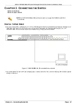
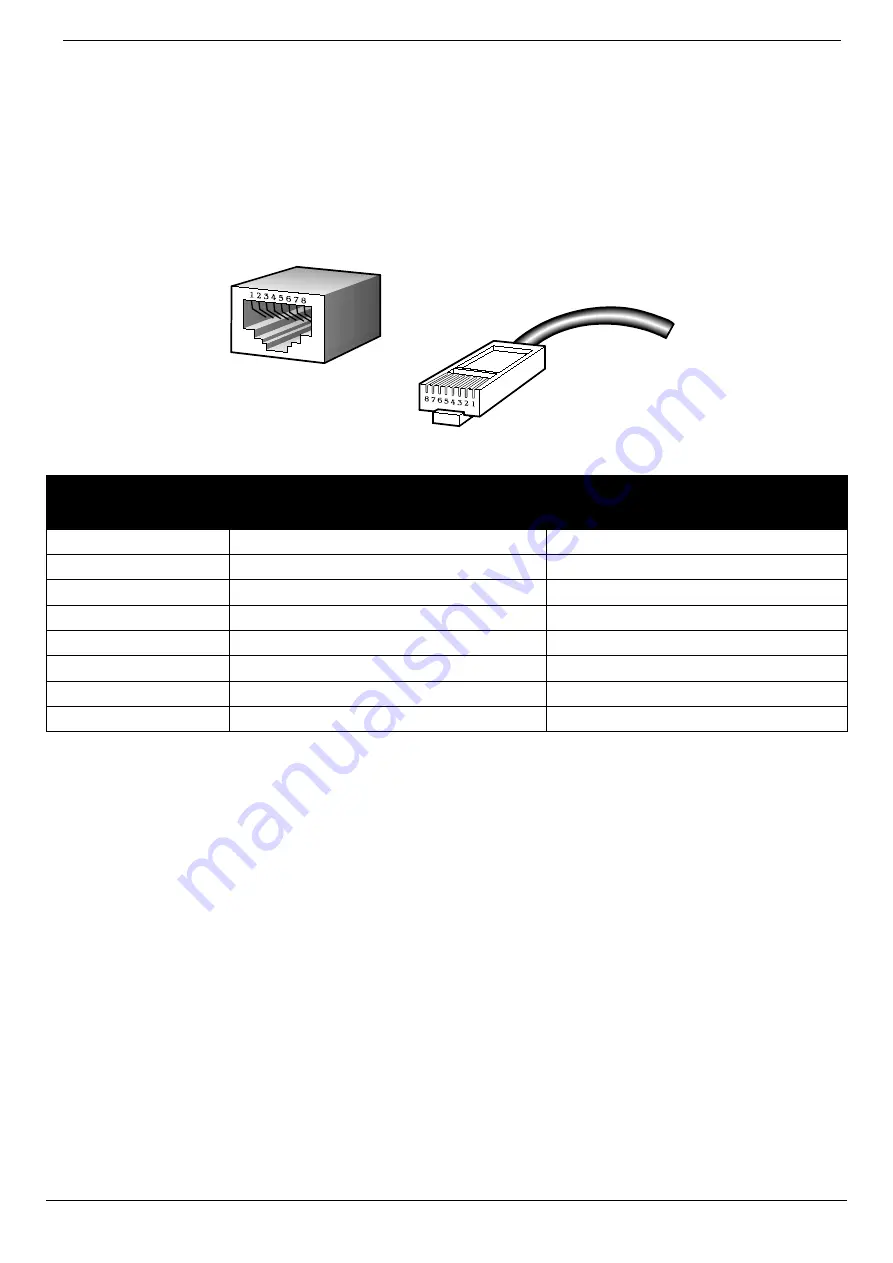
When connecting the Switch to another switch, a bridge or hub, a normal cable is necessary. Please review these
products for matching cable pin assignment.
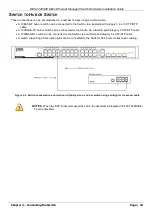
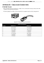
The following diagrams and tables show the standard RJ-45 receptacle/connector and their pin assignments.
Figure B- 1. The standard RJ-45 port and connector
RJ-45 Pin Assignments
Contact
MDI-X Port
MDI-II Port
1
RD+ (receive)
TD+ (transmit)
2
RD- (receive)
TD- (transmit)
3
TD+ (transmit)
RD+ (receive)
4
1000BASE-T
1000BASE-T
5
1000BASE-T
1000BASE-T
6
TD- (transmit)
RD- (receive)
7
1000BASE-T
1000BASE-T
8
1000BASE-T
1000BASE-T