background image

5  Configuration


D-Link Web Smart Switch User Manual


From Port: 

The beginning of a consecutive group of ports may be configured starting with the selected port.


To Port:

 The ending of a consecutive group of ports may be configured starting with the selected port. 

Port Priority (0-65535):

 Displays the LACP priority value for the port. Default is 128. 

Activity:

 There are two different roles of LACP ports: 

Active - 

Active LACP ports are capable of processing and sending LACP control frames. This allows 

LACP compliant devices to negotiate the aggregated link so the group may be changed dynamically 
as needs require. In order to utilize the ability to change an aggregated port group, that is, to add or 
subtract ports from the group, at least one of the participating devices must designate LACP ports as 
active. Both devices must support LACP. 


Passive - 

LACP ports that are designated as passive cannot initially send LACP control frames. In 

order to allow the linked port group to negotiate adjustments and make changes dynamically, one 
end of the connection must have "active" LACP ports. 

Timeout:

 Specify the administrative LACP timeout. The possible field values are: 

Short (3 Sec) 

- Defines the LACP timeout as 3 seconds.   

Long (90 Sec) 

- Defines the LACP timeout as 90 seconds. This is the default value.  


Click 

Apply 

to implement the changes made. 


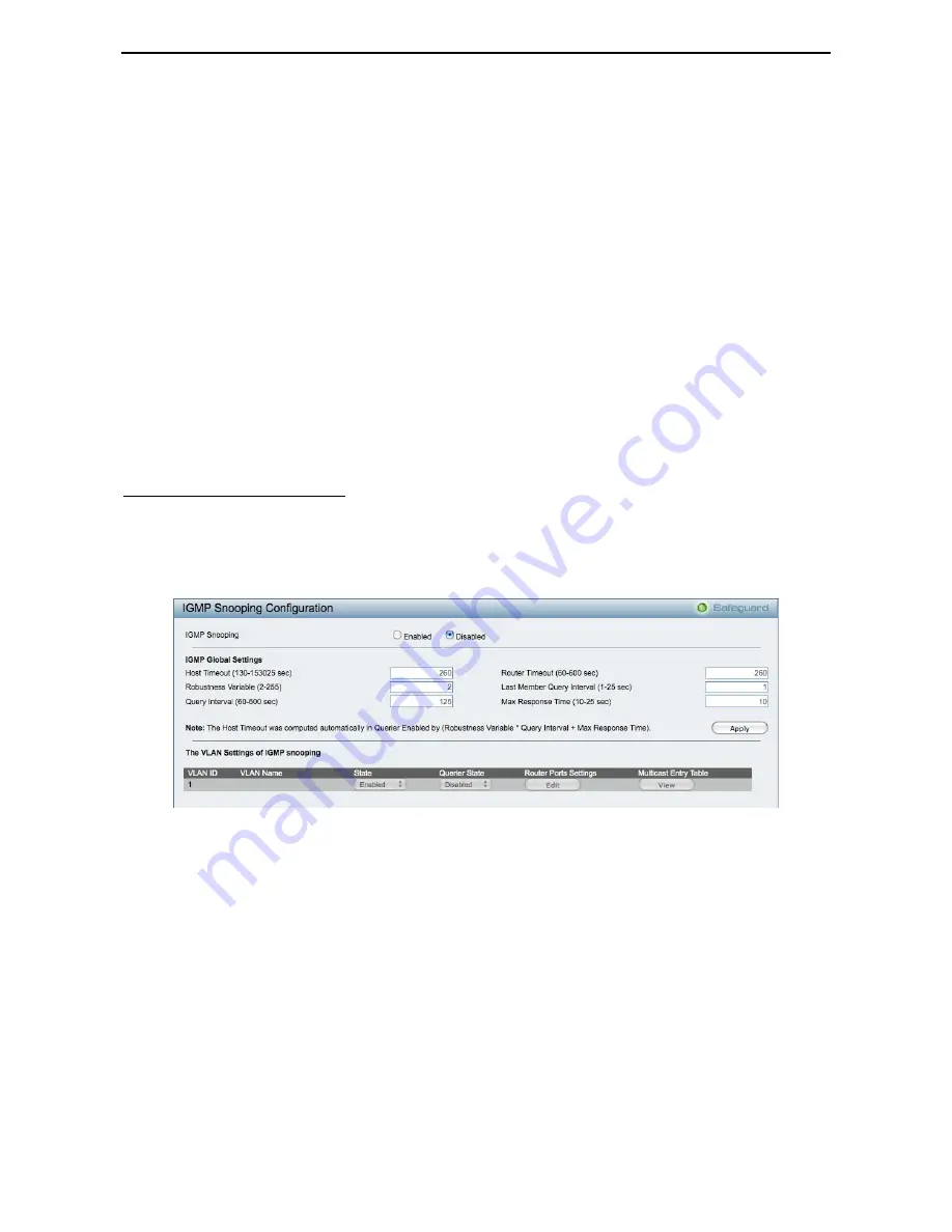
Configuration > IGMP Snooping 

With Internet Group Management Protocol (IGMP) snooping, the Web Smart Switch can make intelligent 
multicast forwarding decisions by examining the contents of each frame’s Layer 2 MAC header.  

IGMP snooping can help reduce cluttered traffic on the LAN. With IGMP snooping enabled globally, the Web 
Smart Switch will forward multicast traffic only to connections that have group members attached. 

The settings of IGMP snooping is set by each VLAN individually.  


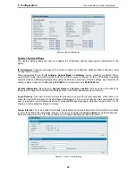
Figure 60 – Configuration > IGMP Snooping Configuration 


By default, IGMP is disabled. If enabled, the IGMP Global Settings will need to be entered: 


Host Timeout (130-153025 sec):

 This is the interval after which a learned host port entry will be purged. For 

each host port learned, a 'Port Purge Timer' runs for 'Host Port Purge Interval'. This timer will be restarted 
whenever a report message from host is received over that port. If no report messages are received for 'Host 
Port Purge Interval' time, the learned host entry will be purged from the multicast group. The default value is 
260 seconds. 

Robustness Variable (2-255 sec):

 The Robustness Variable allows adjustment for the expected packet loss 

on a subnet.  If a subnet is expected to be lossy, the Robustness Variable may need to be increased.  The 
Robustness Variable cannot be set to zero, and it SHOULD NOT be.  Default is 2 seconds.


Query Interval (60-600 sec):

 The Query Interval is the interval between General Queries sent. By adjusting 

the Query Interval, the number of IGMP messages can be increased or decreased; larger values will cause 
IGMP Queries to be sent less often. Default value is 125 seconds. 

Router Timeout (60-600 sec):

 This is the interval after which a learned router port entry will be purged. For 

each router port learned, a 'Router Port Purge Timer' runs for 'Router Port Purge Interval'. This timer will be 
restarted whenever a Query control message is received over that port. If no Query control messages are 

3

3

5

5


Summary of Contents for DES-1228 - Web Smart Switch

Page 1: ......

Page 2: ...ement Options 7 Using Web based Management 7 Supported Web Browsers 7 Connecting to the Switch 7 Login Web based Management 8 Smart Wizard 8 Web based Management 8 SmartConsole Utility 8 SmartConsole...

Page 3: ...IGMP Snooping 35 Configuration Port Mirroring 36 Configuration Loopback Detection 37 Configuration SNTP Settings Time Settings 38 Configuration SNTP Settings TimeZone Settings 38 Configuration Spannin...

Page 4: ...Ethernet Technology 61 Fast Ethernet Technology 61 Switching Technology 61 Appendix B Technical Specifications 62 Hardware Specifications 62 Key Components Performance 62 Port Functions 62 Physical E...

Page 5: ...Usage In this guide the term Switch first letter capitalized refers to the Smart Switch and switch first letter lower case refers to other Ethernet switches Some technologies refer to terms switch br...

Page 6: ...or gateway devices Network Security D Link s innovative Safeguard Engine function protects the switches against traffic flooding caused by virus attacks Additional feature like 802 1X port based authe...

Page 7: ...ink Act Speed LED 25F 26F 25T 26T 27 28 The Link Act Speed LED flashes which indicates a network link through the corresponding port Blinking indicates that the Switch is either sending or receiving d...

Page 8: ...ch installation and operation it is recommended that you Visually inspect the power cord to see that it is secured fully to the AC power connector Make sure that there is proper heat dissipation and a...

Page 9: ...operation of the equipment is not compromised C Mechanical Loading Mounting of the equipment in the rack should be such that a hazardous condition is not achieved due to uneven mechanical loading D C...

Page 10: ...tion D Link Web Smart Switch User Manual Figure 6 Plugging the switch into an outlet Power Failure As a precaution the switch should be unplugged in case of power failure When power is resumed plug th...

Page 11: ...ing the SmartConsole Utility you do not need to change the IP address of your PC and it is easier to initialize multiple Smart Switches Please refer to the following installation instructions for the...

Page 12: ...st This will automatically load the web configuration in your web browser When the following login box appears enter the password then press OK to entering the Web based Management Utility The default...

Page 13: ...nd use the SmartConsole Utility to discover the Smart Switches Option 2 Follow these steps to install the SmartConsole Utility manually 1 Insert the Utility CD into your CD Rom DVD Rom Drive 2 From th...

Page 14: ...t Figure 10 SmartConsole Utility SmartConsole Settings The SmartConsole Settings at the left has five icons Utility Settings Log Trap File and Help Utility Settings Click this icon to launch the Utili...

Page 15: ...g Trap Click this icon to launch the Trap window Click View Trap to show the events of the SmartConsole Utility and the device Date Time indicates when the trap message was received IP denotes where i...

Page 16: ...of the Device List as default for the next time the SmartConsole Utility is used Monitor Save As Records the setting of the Device List in an appointed filename and file path Monitor Load Manually loa...

Page 17: ...tons for the Device List Device Settings Select a switch from the Device List Click on this icon to launch the Device Settings window Here you can configure the Product Name IP Address Gateway Subnet...

Page 18: ...the correct password of device and then click Upgrade The state will show OK after completion and Fail is firmware upgrade fails or cannot be completed for any reason Figure 18 Firmware Upgrade CAUTIO...

Page 19: ...nt by double clicking the device in the device list Add Delete and Discover the device Click the Discovery button to display all the Web Smart devices located in the same domain with the management PC...

Page 20: ...tware version of the Utility Product Name Displays the device product name System Name Displays the appointed device system name DHCP Specify if the device gets the IP address from a DHCP server Locat...

Page 21: ...Link Web Smart Switch If you do not plan to change anything click Exit to leave the Wizard and enter the Web Interface You can also skip it by clicking Don t show Smart Wizard next time for logon the...

Page 22: ...Settings in the Web Interface By default thet SNMP Setting is Disabled Click Enabled enter Community names and then click Apply to activate SNMP Setting Read_Only Community Allows authorized managemen...

Page 23: ...Select DHCP to have the switch obtain an IP address from a DHCP server in the network Figure 25 Configure System IP address in Smart Wizard NOTE Changing the system IP address will disconnect you from...

Page 24: ...osing different functions in the Function Tree you can change all the settings in the Main Configuration Screen The main configuration screen will show the current status of your Switch by clicking th...

Page 25: ...ew or edit the log file by using text editor e g Notepad Figure 30 Save Log Tool Bar Tool Menu The Tool Menu offers global function controls such as Reset Reset System Reboot Device Configuration Back...

Page 26: ...nt settings to your disk Click Browse to browse your inventories for a saved backup settings file Click Restore after selecting the backup settings file you want to restore TFTP TFTP Trivial File Tran...

Page 27: ...rom Click Backup to save the firmware to the TFTP server Click Upgrade after selecting the firmware file you want to restore CAUTION Do not disconnect the PC or remove the power cord from device until...

Page 28: ...ng to link to Configuration Spanning Tree STP Global Settings Default is disabled Port Mirroring Click Setting to link to Configuration Port Mirroring Default is disabled Storm Control Click Setting t...

Page 29: ...t mask is 255 255 255 0 System Information By entering a System Name and System Location the device can more easily be recognized through the SmartConsole Utility and from other Web Smart devices on t...

Page 30: ...wn Copper port connection information RSTP Port State Change Events of a RSTP port state changes Firmware Upgrade State Information of firmware upgrade success or failure System Port Settings In the P...

Page 31: ...devices SNMP enables network management stations to read and modify the settings of gateways routers switches and other network devices Use SNMP to configure system features for proper operation moni...

Page 32: ...ge events as well as report errors and informational messages Message severity determines a set of event message will be sent Click Enable so you can start to configure the related settings of remote...

Page 33: ...VLAN without having to change any physical connections The IEEE 802 1Q VLAN Configuration page provides powerful VID management functions The original settings have the VID as 1 no default name and al...

Page 34: ...e when used in a small network where a L3 routing device is absent or if the resource to be shared is not capable of supporting tagged VLAN for example a printer The example below is a typical applica...

Page 35: ...other VLANs for example port 6 and 7 respectively Therefore we have three VLANs that share some common ports but their original membership ports are still separated from each other for example port 5...

Page 36: ...1Q Management VLAN Configuration Voice VLAN Voice VLAN Setting Voice VLAN is a feature that allows you to automatically place the voice traffic from IP phone to an assigned VLAN to enhance the VoIP s...

Page 37: ...VLAN OUI Setting This window allows the user to configure the user defined voice traffic s OUI An Organizationally Unique Identifier OUI is the first three bytes of the MAC address This identifier un...

Page 38: ...king groups Two types of link aggregation can be selected Static Static link aggregation LACP LACP Link Aggregation Control Protocol is enabled on the device LACP allows for the automatic detection of...

Page 39: ...eader IGMP snooping can help reduce cluttered traffic on the LAN With IGMP snooping enabled globally the Web Smart Switch will forward multicast traffic only to connections that have group members att...

Page 40: ...ments for controlling the frequency of IGMP traffic on a subnet Default is 10 seconds Querier State D Link Smart Switch is able to send out the IGMP Queries to check the status of multicast clients De...

Page 41: ...orts into port mirroring None Turns off the mirroring of the port Click all to remove all ports from mirroring Configuration Loopback Detection The Loopback Detection function is used to detect the lo...

Page 42: ...re displayed in the Time Settings page Figure 65 Configuration SNTP Settings Time Settings Clock Source Specify the clock source by which the system time is set The possible options are Local Indicate...

Page 43: ...ply to implement changes made Configuration Spanning Tree STP Global Settings The Switch implements two versions of the Spanning Tree Protocol the Rapid Spanning Tree Protocol RSTP as defined by the I...

Page 44: ...between transmissions of configuration messages by the root device thus stating that the Switch is still functioning The default is 2 seconds Forward Delay 4 30 sec This sets the maximum amount of ti...

Page 45: ...e True parameter designates the port as an edge port Edge ports cannot create loops however an edge port can lose edge port status if a topology change creates a potential for a loop An edge port norm...

Page 46: ...ifferent Storm type from Broadcast Only Multicast Broadcast and Multicast Broadcast Unknown Unicast Threshold 64Kbps N If storm control is enabled default is disabled the threshold is from of 64 1 024...

Page 47: ...network administrators to reserve bandwidth for important functions that require a larger bandwidth or that might have a higher priority such as VoIP voice over Internet Protocol web browsing applica...

Page 48: ...as reached its egress weight the system will process the packets in the next level even if there are remaining packets D Link Smart Switch system s weight of priority levels are 8 Highest 4 High 2 Med...

Page 49: ...worm attacks This option is enabled by default Figure 74 Security Safeguard Engine Security Port Security Port Security is a security feature that prevents unauthorized computers with source MAC addr...

Page 50: ...to the client Default is 24 seconds ReAuthEnabled This function is to determine whether regular re authentication will take place on this port s When the 802 1X function is enabled the switch sends a...

Page 51: ...CP Server or Gateway By default this feature is Off disabled Figure 77 Security Static Mac Address To initiate the removal of auto learning for any of the uplink ports click On to enable this feature...

Page 52: ...Renews the details collected and displayed Clear All Counters To reset the details displayed TxOK Number of packets transmitted successfully RxOK Number of packets received successfully TxError Numbe...

Page 53: ...onfiguration D Link Web Smart Switch User Manual Previous Page Go back to the Statistics main page Refresh To renew the details collected and displayed Clear Counter To reset the details displayed 4 4...

Page 54: ...d of the cable is simply disconnected Test Failed means some other errors occurred during cable diagnostics Please select the same port and test again Cable Fault Distance meters Indicates the distanc...

Page 55: ...from this MAC address IPv4 Addresses Indicates ACL action will be on packets from this IPv4 source address To Specify the destination of accessible packets The possible values are Any Indicates ACL ac...

Page 56: ...eria Figure 84 ACL ACL Profile List The contents of Access Profile List table include Profile ID Indicates the profile Identification number The possible configured profile IDs are 1 50 and profile ID...

Page 57: ...ering mask and click Create when done A filtering mask is to specify the digit that you want to check For example if you want to check a network of 192 168 1 0 24 then you should enter the IP mask as...

Page 58: ...the Ethernet Type value Destination IP Address Specify the Destination IP address Source IP Address Specify the Source IP address DSCP Specify the DSCP value IP Protocol The L4 protocol above IP Poss...

Page 59: ...o help find a previously configured ACL entry To search for an entry enter the profile ID from the drop down menu select a port that you wish to view define the state and click Find The table on the l...

Page 60: ...e 90 Command Prompt The user session is automatically terminated if idle for the login timeout period The default login timeout period is 5 minutes To change the login timeout session please refers to...

Page 61: ...the TFTP server tftp ip address The IP address of the TFTP server filename The filename of the firmware or switch configuration file on the TFTP server You need to specify the DOS path if the file is...

Page 62: ...es integer 1 255 Specify how many ping requests will be sent to the target IP address timeout integer 1 99 Specify the timeout interval waiting the ping reply for target IP address Example DES 1228 pi...

Page 63: ...mmand Show switch The command displays the status of the switch Syntax show switch Example DES 1228 show switch System name System Contact System Location System up time 0 days 6 hrs 32 min 17 secs Sy...

Page 64: ...DES 1228 config account admin password admin DES 1228 Figure 99 The config account admin password command Save The command saves the configuration changes to the memory Syntax save Example DES 1228 sa...

Page 65: ...e over unshielded twisted pair UTP cabling outfitting your network with a powerful 1000 Mbps capable backbone server connection which will create a flexible foundation for the next generation of netwo...

Page 66: ...50 RX 1310nm 10km DEM 330R 1000Base BX TX 1310 RX 1550nm 10km DEM 331T 1000Base BX TX 1550 RX 1310nm 40km DEM 331R 1000Base BX TX 1310 RX 1550nm 40km DEM 220T 100Base BX TX 1550 RX 1310nm 20km DEM 220...

Page 67: ...ty D Link proprietary CLI SNMP support DHCP client Trap setting for destination IP system events fiber port events twisted pair port events Port access control Web based configuration backup restorati...

Page 68: ...of the equipment in a rack should be such that the amount of air flow required for safe operation of the equipment is not compromised C Mechanical Loading Mounting of the equipment in the rack should...

Page 69: ......

Reviews: