background image

External Features

9

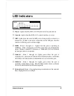
LED Indicators


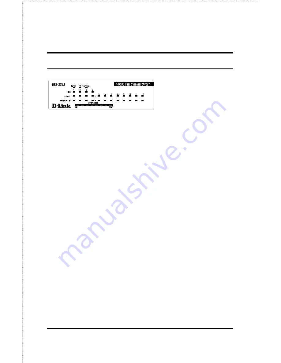
Power  Lights when the DES-2212 Ethernet switch is powered on.


Console  Lights when the DES-2212 console interface is in use.


MII  Lights when the switch’s MII port is being used to connect to a
transceiver.  If there is an active connection on the MII port, then the
Link/Act LED for port 2x will also light.


100M  (Ports 1 through 4 )  Lights when the port is operating at
100Mbps.  Ports 1 through 4 are NWay ports that can automatically
detect whether 10BASE-T Ethernet or 100BASE-TX Fast Ethernet
twisted-pair cable is connected.


Link/Act  (Ports 1 through 12) Lights green when the port is
connected to a powered-on Ethernet/Fast Ethernet station, and blinks
off briefly when information is transmitted or received on the port.


FDX/Col  (Ports 1 through 12) Lights green when the port is
operating in full-duplex mode.  Briefly blinks amber when a collision
occurs on the Ethernet/Fast Ethernet segment.


System Load  Shows a bar graph giving an indication of the network
load, ranging from Low to High.

Summary of Contents for DES-2212

Page 1: ...10 100Mbps Ethernet Fast Ethernet Switch Model DES 2212 User s Guide Rev 02 October 1997 6DES2212 02 Printed In Taiwan RECYCLABLE ...

Page 2: ...h am Geräten befinden sind zu beachten 12 Wird das Gerät über einen längeren Zeitraum nicht benutzt sollten Sie es vom Stromnetz trennen Somit wird im Falle einer Überspannung eine Beschädigung vermieden 13 Durch die Lüftungsöffnungen dürfen niemals Gegenstände oder Flüssigkeiten in das Gerät gelangen Dies könnte einen Brand bzw Elektrischen Schlag auslösen 14 Öffnen Sie niemals das Gerät Das Gerä...

Page 3: ...IN THE PRODUCT DOES NOT EXIST OR WAS CAUSED BY THE CUSTOMER S OR ANY THIRD PERSON S MISUSE NEGLECT IMPROPER INSTALLATION OR TESTING UNAUTHORIZED ATTEMPTS TO REPAIR OR ANY OTHER CAUSE BEYOND THE RANGE OF THE INTENDED USE OR BY ACCIDENT FIRE LIGHTNING OR OTHER HAZARD LIMITATION OF LIABILITY IN NO EVENT WILL D LINK BE LIABLE FOR ANY DAMAGES INCLUDING LOSS OF DATA LOSS OF PROFITS COST OF COVER OR OTHE...

Page 4: ...any software firmware information or memory data of Customer contained in stored on or integrated with any products returned to D Link pursuant to any warranty All products with lifetime warranty have a standard five year warranty To qualify for lifetime warranty the enclosed Product Registration Card must be completed and returned to D Link within ninety 90 days of purchase Warranty service may b...

Page 5: ... provided by third party that the operation of the software products will be uninterrupted or error free or that all defects in the software product will be corrected For any third party products listed in the D Link software product documentation or specifications as being compatible D Link will make reasonable efforts to provide compatibility except where the non compatibility is caused by bug o...

Page 6: ...comply with the limits for a Class A digital device pursuant to Part 15 of the FCC Rules These limits are designed to provide reasonable protection against harmful interference when the equipment is operated in a commercial environment This equipment generates uses and can radiate radio frequency energy and if not installed and used in accordance with this user s guide may cause harmful interferen...

Page 7: ... 2 Management 2 100Mbps Fast Ethernet Introduction 3 100BASE TX Technology Overview 3 Cables and Connectors 3 Topology 4 Network 4 Hubs 5 Connectivity Rules 5 Ethernet Switching Introduction 6 2 EXTERNAL FEATURES 7 Front Panel 7 LED Indicators 9 Rear Panel 10 3 INSTALLATION 13 Unpacking the Switch 13 Installing the Switch 14 Location 14 ...

Page 8: ... User Privileges 24 Login On The Switch Console By Registered Users 27 Changing your Password 28 Adding and Deleting Users 29 Setting up the Switch 31 TCP IP Settings 31 Out of band management and console settings 33 Software Updates 34 SNMP Information and Console Timeout 35 SNMP Traps 37 SNMP Security Community Names 38 Switch Configuration 38 Controlling Individual Ports 39 Forwarding Configura...

Page 9: ... Reset 51 Factory Reset 52 6 PRODUCT SPECIFICATIONS 55 General 55 LED Indicators 56 Environmental and Physical 56 7 CABLES AND CONNECTORS 57 10BASE T 100BASE TX Connectors 57 Crossover Cable 59 MII Connector 59 RS 232 DB9 Pin Specification 61 8 BOOT CONFIGURATION FILE 65 9 INDEX 68 ...

Page 10: ......

Page 11: ...stations and to other parts of your network Chapter 5 Using the Console Interface Explains the use of the console interface which you can use to configure the hub with a terminal or telnet connection Appendix A Product Specifications Lists the switch s specifications the standards it meets and certifications it has passed Appendix B Cables and Connectors Gives pinout information for the 10BASE T 1...

Page 12: ......

Page 13: ...management capability Ports The DES 2212 has twelve ports four NWay 10BASE TX Ethernet 100BASE TX Fast Ethernet ports and eight 10BASE T twisted pair Ethernet ports Among the Fast Ethernet ports one of the ports can also use an industry standard MII connector making it possible to interface to different types of 100BASE X Fast Ethernet network media such as 100BASE FX fiber optic cable or 100BASE ...

Page 14: ... security or other purposes The switch supports the IEEE 802 1d Spanning Tree Protocol allowing you to design your network with redundant bridge links Management You can use any network management software supporting SNMP the Simple Network Management Protocol to manage the DES 2212 including D Link s Windows based D View management system The DES 2212 s internal intelligent management agent suppo...

Page 15: ...ps Ethernet users 100Mbps Fast Ethernet is a relatively new standard specified by the IEEE 802 3 networking standards committee It is an extension of the 10Mbps Ethernet standard with the ability to transmit and receive data at 100Mbps while maintaining the CSMA CD Ethernet protocol Since the 100Mbps Fast Ethernet is compatible with all other 10Mbps Ethernet environments it provides a straightforw...

Page 16: ...s The following factors strongly influence the architecture of Fast Ethernet networks The EIA TIA 568 Wiring Standard imposes a 100 meter limit on horizontal runs of twisted pair cables that is connections from the wiring closet to the end station Fast Ethernet s increased operational speed reduces the maximum distance between all elements of the LAN see below The EIA TIA 568 Wiring Standard does ...

Page 17: ...o translations are performed This type of hub connects identical media to the same collision domain for example TX to TX At most two Class II hubs can exist within the same collision domain The cable used to cascade these hubs is called an inter repeater link IRL As mentioned earlier stackable hubs can be used to increase the number of available nodes in a collision domain An entire hub stack coun...

Page 18: ...ut interfering with any other segments This allows the total network capacity to be multiplied while still maintaining the same network cabling and adapter cards For Fast Ethernet networks a switch is an effective way of eliminating problems of chaining hubs beyond the two repeater limit A switch can be used to split parts of the network into different collision domains making it possible to expan...

Page 19: ...5 2 EXTERNAL FEATURES This chapter explains the features visible on the front and rear panels of the DES 2212 Ethernet switch Front Panel A front view of the DES 2212 Ethernet switch is shown below ...

Page 20: ...0Mbps ports ports 1 through 4 are NWay 10BASE T 100BASE TX MDI X ports suitable for connecting directly to Ethernet or Fast Ethernet hosts or other network equipment The NWay feature allows the switch to automatically detect the speed of the network connection 10Mbps Ports The 10Mbps ports ports 5 through 12 are 10BASE TX MDI X ports suitable for connecting directly to Ethernet hosts or other netw...

Page 21: ...orts 1 through 4 are NWay ports that can automatically detect whether 10BASE T Ethernet or 100BASE TX Fast Ethernet twisted pair cable is connected Link Act Ports 1 through 12 Lights green when the port is connected to a powered on Ethernet Fast Ethernet station and blinks off briefly when information is transmitted or received on the port FDX Col Ports 1 through 12 Lights green when the port is o...

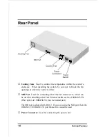
Page 22: ...herwise restrict airflow MII Port Used for connecting Fast Ethernet transceivers which can be used for attaching other Fast Ethernet media such as 100BASE FX fiber optic or 100BASE T4 4 wire twisted pair The MII port is shared with Port 2 If you are using the MII port then the 10BASE T 100BASE TX port labeled 2x cannot be used Power Connector Used for connecting the power cord ...

Page 23: ...External Features 11 Power Switch Used to turn the switch on 1 position or off 0 position ...

Page 24: ......

Page 25: ...ully unpack the contents The carton should contain the following items One DES 2212 Ethernet Fast Ethernet switch One AC power cord Four rubber feet to be used for shock cushioning Eight screws and two mounting brackets This User s Guide Inspect the switch and all accompanying items If any item is damaged or missing report the problem immediately to your dealer ...

Page 26: ...r of the switch for ventilation Install on a sturdy level surface that can support at least the weight of the switch or in an EIA standard size rack For information on rack installation see the next section Rack Mounting When installing the switch on a level surface ensure to attach the rubber feet at the bottom of the device The rubber feet act as cushioning devices Rack Mounting The switch can b...

Page 27: ... should fall within this range To turn on the DES 2212 plug in the provided AC power cord into the power connector at the rear of the system then flip the rocker power switch to the 1 position After turning on the power the Power indicator on the front panel should light It is not necessary to turn off the DES 2212 s power when connecting or disconnecting network cables except for the MII port or ...

Page 28: ...s of the device The fuse and a spare one are contained in a fuse case located just beneath the AC power connector When replacement becomes necessary pry open this case with a small screwdriver and replace the damaged fuse You may also purchase a new 2 0A fuse which is readily available in most local stores Fuse Spare Fuse WARNING DO NOT defeat the purpose of the fuse by using a jumper such as a wi...

Page 29: ...ch port means the ports are MDI X ports which connect to workstations and servers using straight through twisted pair cables and to hubs or switches using crossover cables Ports 1 through 4 are NWay 10 100Mbps ports that can also be used for 10BASE T connection provided you don t need to use the ports for 100BASE TX To connect a network station use ordinary Ethernet twisted pair cable Category 3 o...

Page 30: ...y at both ends of the cable Check the continuity of the wires in the cable as well as the pin assignments on the RJ 45 connectors Be sure that the network station to which the port is connected is plugged in and powered on Be sure that you are using a Category 3 or better straight through not crossover cable If you are connecting the switch to an Ethernet hub or another Ethernet switch with an MDI...

Page 31: ... of the same port If you are using the Uplink port you cannot use Port 1 and vice versa MII Connection The switch s back panel features an industry standard MII connector allowing you to attach transceivers for other types of 100BASE X media such as 100BASE FX or 100BASE T4 To connect a device using the switch s MII port 1 Make sure that the switch is turned off whenever connecting a transceiver t...

Page 32: ...20 Making Network Connections NOTE Port 2 and the MII port form one logical port Only one of these ports can be used at any given time ...

Page 33: ...ch for management using D View or another SNMP based network management system This chapter describes how to use the console interface to access the switch change its settings and monitor its operation Connecting to the Switch You can use the console interface by connecting to the switch using an ordinary RS 232C serial cable and a VT100 compatible terminal or a computer running an ordinary termin...

Page 34: ...owing conventions 1 Items after a colon are read only values displayed for information purposes The cursor cannot be moved to these items 2 Items in angle brackets can be toggled on or off using the space bar 3 Items in square brackets can be changed by typing in a new value You can use the backspace and delete keys to erase characters behind and in front of the cursor 4 The up and down arrow keys...

Page 35: ...section tells how to log onto the Switch Note The passwords used to access the Switch are case sensitive therefore S is not the same as s When you first connect to the Switch you will be presented with the first login screen shown below Figure 6 1 Initial screen first time connecting to the Switch Move the cursor to OK and press Enter Note Leave the User Name and Password fields blank You will see...

Page 36: ...nt Change Menu appears 1 Choose Create New User from the User Account Change Menu and the Create New User Menu appears 2 Enter the new user name and assign an initial password Determine whether the new user should have Super User or General User privileges 3 Choose SAVE and press Enter to let the user addition take effect 4 Choose EXIT to leave the Create New User menu Super and General User Privi...

Page 37: ... The main menus shown are the menus for users with Super User and General User privileges Figure 6 3 Main Menu for Super User Figure 6 4 Main Menu for General User The following table summarizes Super User and General User privileges Menu Super User General User Privilege ...

Page 38: ...om Filtering Table Yes Yes view only Protocol Parameters Yes Yes view only STAP Port Parameters Yes Yes view only Out of Band Console Configuration Yes Yes view only User Account Change Create New User Yes No Change Access Delete Users Yes No Change Password Yes Yes SNMP Trap Manager Configuration Yes Yes view only SNMP Manager Config Yes Yes view only System Reset Yes No Software Update Yes No Fa...

Page 39: ...lows Login On The Switch Console By Registered Users Figure 6 5 Login Screen To log in 1 Type in your user name and press Enter 2 Type in your password and press Enter 4 If the Switch is not used within five 5 minutes the following message appears at the bottom of the console s main menu Console time out press ENTER to continue At this time press ENTER and login screen will be displayed ...

Page 40: ...s Changing your Password To change your user password 1 Choose User Account Change from the main menu 2 Choose Change Password Figure 6 6 Change Password 3 Type in your user name and press Enter 4 Type in your old password and press Enter 5 Type in the new password you have chosen and press Enter Type in the same new password in the following blank to verify that you have not mistyped it 6 Choose ...

Page 41: ...name and password Up to three of these user names can be defined The console interface will not let you delete the current logged in user however in order to prevent accidentally deleting all of the users with Super User privilege Only users with the Super User privilege can add new and delete users Adding a New User To add a new user 1 Choose User Account Change from the main menu Figure 6 7 User...

Page 42: ...r privileges Figure 6 8 Adding a New User 4 Choose SAVE and press Enter to let the user addition take effect 5 Choose EXIT to leave the Create New User menu Deleting a User To delete a user 1 Choose User Account Change from the main menu 2 Choose Delete Users from the User Account Change menu 3 Toggle the Delete field of the user you wish to remove to Yes ...

Page 43: ...u to be able to manage the switch from an SNMP based Network Management System such as D Link s D View or to be able to access the switch using the Telnet protocol TCP IP Settings The switch needs to have a TCP IP address assigned to it so that the network management system or Telnet client can find it on the network The TCP IP Parameters Configuration Menu allows you to change the settings for th...

Page 44: ...x xxx where each xxx is a number represented in decimal between 0 and 255 If no subnetting is being done the value should be 255 0 0 0 for a Class A network 255 255 0 0 for a Class B network and 255 255 255 0 for a Class C network Default Gateway IP address that determines where frames with a destination outside the current subnet should be sent This is usually the address of a router or a host ac...

Page 45: ...rate used for SLIP communications The following fields can be set System Restart Out of Band Baud Rate determines the serial port bit rate that will be used the next time the switch is restarted Applies only when the serial port is being used for out of band SLIP management it does not apply when the port is used for the console port Available speeds are 2400 9600 19200 and 38400 bits per second O...

Page 46: ...ng TFTP the Trivial File Transfer Protocol and BOOTP the BOOTstrap Protocol You can use the Software Update menu to control this feature The fields you can set on this menu are Software Update Determines whether or not the switch will try to look for a configuration file over the network If set to Disable none of the fields below have any effect Software Update Mode Set to either Network or Out of...

Page 47: ... pathname of the CFG file on your hard disk This entry is used only if your boot protocol is TFTP ONLY if you are using BOOTP TFTP mode or if Use Bootp to get IP after start up is enabled the pathname will be obtained from the BOOTP server For more information about DES 2212 configuration files consult the appendix For detailed information about using the TFTP and BOOTP servers consult the D View ...

Page 48: ...name has been assigned System Location corresponds to the SNMP MIB II variable system sysLocation and is used to indicate the physical location of the switch for administrative purposes System Contact corresponds to the SNMP MIB II variable sysContact and is used to give the name and contact information for the person responsible for administering the switch Figure 6 13 System Configuration Menu T...

Page 49: ...witch allows traps to be routed to up to four different network management hosts Figure 6 14 SNMP Trap Manager Configuration Menu The following trap parameters can be set IP Address gives the IP address of the network management station to receive the trap SNMP Community String determines the SNMP community name to be included in the trap request Status determines whether this trap entry is valid ...

Page 50: ... DES 2212 allows up to four different community names to be defined and the access rights for each community can be separately set to either read only or read write The community names public and private are defined by default you can change these names in addition to adding others You will need to coordinate these names with the community name settings you use in your network management system Fi...

Page 51: ...manually partitioned Setting the Port State to Disabled will isolate the port from the rest of the network Port Status Shows whether or not there is a good link to a station connected to the port Auto Negotiation Determines whether or not the NWay automatic speed detection feature is enabled for the port Media Speed 100 10Mbps Displays the transmission speed of the selected port either 100 Ports 1...

Page 52: ...n what segment the frame s destination is connected to and forward the frame to only that segment If the switch hasn t yet learned what segment a station belongs to it forwards the packet to all ports To display the forwarding table the switch s current idea of what stations are attached to what ports 1 Choose Spanning Tree Algorithm Parameters from the main menu 2 Choose Forwarding Table Figure 6...

Page 53: ...oose Spanning Tree Algorithm Parameters from the main menu 2 Choose Custom Filtering Table Figure 6 18 Custom Filtering Table 3 In the Source Address field enter the Ethernet MAC address of the station in the form xx xx xx xx xx xx each xx must be a hexadecimal number between 00 and FF 4 In the Source Port field type in the port number to which the station is to be connected For example the value ...

Page 54: ...elects the path with the lowest path cost as the active path while blocking other paths and using them as backups Automatic topology reconfiguration If a path for which there is a backup path fails the backup path will be automatically activated and the spanning tree protocol will automatically reconfigure the network topology STP parameters are mainly used to determine the root bridge and root po...

Page 55: ...n the same segment If all bridges have the same root path cost then the one with the lowest bridge identifier becomes the designated bridge Since the root path cost of the root bridge is zero the root bridge automatically becomes the designated bridge for the segments connected onto it Bridge Identifier This is a combination of the bridge priority a parameter you can set and the bridge MAC address...

Page 56: ...he port priority the higher the chance the port has for becoming the root port Port priority ranges from 0 to 255 with 0 being the highest port priority Path Cost Use this parameter to specify preferred paths on the network The smaller the path cost the more chance the port of becoming the root port By convention a 10 Mbps LAN port has a path cost of 100 while a 100 Mbps port has a path cost of 10...

Page 57: ... 15 1 2 1 2 1 2 Setting Spanning Tree Protocol Parameters To set the STP bridge parameters for the switch 1 Choose Spanning Tree Algorithm Parameters from the main menu 2 Choose Protocol Parameters from the Spanning Tree Algorithm Parameters menu 3 The Protocol Parameters menu displays the current status of the Spanning Tree Algorithm s operation on the DES 2212 and allows you to change several of...

Page 58: ...since the DES 2212 was turned on Designated Root The MAC Ethernet address of the bridge switch on the network that has been chosen as the STA root Root Cost Displays the cost for the path between this switch and the root bridge If the DES 2212 is the root bridge then this field displays zero Root Port Identifies the port on this bridge that offers the least path cost from this bridge to the root b...

Page 59: ...consecutive transmissions of BPDU packets sent by the root bridge to inform all other bridges that it is indeed the root bridge If you set a Bridge Hello Time for a bridge that is not the root bridge the setting will be used if and when this bridge becomes the root bridge Bridge Hello Time ranges from 1 to 10 seconds with 2 seconds as default Bridge Forward Delay Bridge Forward Delay ranges from 4...

Page 60: ...ndicates the current state of the port A port can have the following states Disabled Blocking Listening Learning Forwarding and Broken A broken state means that the link on the port has been broken because the port is malfunctioning Blocking means that the port has been blocked because it is neither a root port nor a designated port In STP only root and designated ports are used Designated Root In...

Page 61: ...s used in conjunction with the physical port number to compute the port ID used for selecting the root port The lower the port ID the more likely the port is to become the root port Monitoring the Switch The switch supports several monitoring functions allowing you to keep statistics on the operation of each port Displaying Port Statistics The switch collects Ethernet transmission statistics for e...

Page 62: ...es local and dropped packets Total Octs Rx Counts the number of bytes octets received on the port in both good frames and error frames Multicast Rx Frames Counts the number of good multicast frames received This includes local and dropped multicast packets Broadcast Rx Frames Counts the number of good broadcast frames received This includes local and dropped broadcast packets Rx Good Frames Counts...

Page 63: ...r at 0 Resetting the Switch You can use the console interface to reset the switch either doing a System Reset which restarts the switch and is identical to powering the hub off and back on again or a Factory Reset which sets all of the switch s parameters to what they were when the switch was delivered from the factory System Reset To perform a system reset 1 Choose System Reset from the main menu...

Page 64: ...ng a factory reset be absolutely certain that this is what you want to do Once the reset is done all of the switch s settings stored in NVRAM including TCP IP parameters SNMP parameters the enabled disabled settings of ports security settings etc will be erased and restored to their factory default settings 1 Choose Factory Reset NV RAM to Default Value from the main menu ...

Page 65: ...de Using the Console Interface 53 Figure 6 23 Factory Reset 2 Move the cursor to Yes to confirm the reset and press Enter The switch should restart and all of its parameters will be reset to their default values ...

Page 66: ......

Page 67: ...peater ANSI X3T9 5 Twisted Pair Transceiver Topology Star Protocol CSMA CD Network Data Transfer Rate 10Mbps 100Mbps Number of Ports 8 10BASE T ports 4 10BASE T 100BASE TX NWay ports Network Media 10BASE T UTP Cat 3 4 5 100 ohm unshielded twisted pair 100m max 100BASE TX UTP Cat 5 100 ohm unshielded twisted pair 100m max ...

Page 68: ...sical Power Supply 100 to 240 VAC 50 or 60 Hz internal universal power supply Power Consumption 40 watts max Dimensions 441mm 207mm 43mm 1U height 19 inch rack mountable Weight approx 3kg Operating Temperature 0 to 50 C Storage Temperature 20 to 55 C Humidity 5 to 95 non condensing DC Fans two 40mm 40mm Emissions FCC Class A CE Mark VCCI Class 1 Safety UL CSA TUV GS ...

Page 69: ...me Ports 5 through 12 are MDI X 10BASE T Ethernet ports 10BASE T 100BASE TX connection requires a twisted pair cable at most 100 meters long with RJ 45 connectors at both ends You can use shielded twisted pair cable or 0 4 0 6 mm 22 26 AWG 8 wire unshielded twisted pair cable for the connection 100BASE TX connection requires Category 5 twisted pair cabling The following diagram and table show the ...

Page 70: ...act MDI X Signal MDI Signal 1 RD receive TD transmit 2 RD receive TD transmit 3 TD transmit RD receive 4 Not used 5 Not used 6 TD transmit RD receive 7 Not used 8 Not used TD RD 1 1 3 3 6 6 RD TD TD RD RD TD 2 2 Workstation MDI Switch MDI X Straight through Cable ...

Page 71: ... other end of the cable connect wires 1 and 2 to contacts 3 and 6 respectively Likewise connect wires 3 and 6 to contacts 1 and 2 Refer to the following diagram RD RD 1 1 3 3 6 6 TD TD RD RD TD TD 2 2 Hub MDI X Switch MDI X Crossover Cable MII Connector The MII Media Independent Interface is a standard 40 pin connector that you can use to connect other types of 100Mbps network media to your DES 22...

Page 72: ... 6 RXD 1 Receive Data 1 bit 26 Ground 7 RXD 0 Receive Data 0 bit 27 Ground 8 RX_DV Receive Data Valid 28 Ground 9 RX_CLK Receive Clock 29 Ground 10 RX_ER Receive Error 30 Ground 11 NOT USED Not Used 31 Ground 12 TX_CLK Transmit Clock 32 Ground 13 TX_EN Transmit Enable 33 Ground 14 TXD 0 Transmit Data 0 bit 34 Ground 15 TXD 1 Transmit Data 1 bit 35 Ground 16 TXD 2 Transmit Data 2 bit 36 Ground 17 T...

Page 73: ... workstation emulating a VT 100 terminal The connection can be either local or remote through a modem For a remote connection a modem cable with a 9 pin male connector on the hub side is needed The figures below show the connections necessary for local and remote connection to 9 pin and 25 pin RS 232 devices Term inal PC Serial Port DTE DB 9 Console Port DCE DB 9 9 RXD 2 TxD 3 DTR 4 SG 5 DSR 6 RTS...

Page 74: ...G 5 DSR 6 RTS 7 CTS 8 DCD 1 RXD 3 TxD 2 DTR 20 SG 7 DSR 6 RTS 4 CTS 5 DCD 8 Local Connection to 25 Pin Serial Port Modem DCE DB 9 Console Port Connector DCE DB 9 9 RXD 2 TxD 3 DTR 4 SG 5 DSR 6 RTS 7 CTS 8 DCD 1 9 RXD 2 TxD 3 DTR 4 SG 5 DSR 6 RTS 7 CTS 8 DCD 1 Remote Modem Connection to 9 Pin Serial Port ...

Page 75: ...bles and Connectors 63 Modem DCE DB 25 Console Port DCE DB 9 9 RXD 2 TxD 3 DTR 4 SG 5 DSR 6 RTS 7 CTS 8 DCD 1 RXD 3 TxD 2 DTR 20 SG 7 DSR 6 RTS 4 CTS 5 DCD 8 Remote Modem Connection to 25 Pin Serial Port ...

Page 76: ......

Page 77: ...ace The configuration file is a text file usually stored on the server with a CFG extension It can be up to 10 kilobytes long Lines beginning with are considered comments which are ignored by the hub All other lines are commands which are interpreted by the switch The configuration file commands accepted by the hub are sysdescr string Takes string as the System Name corresponding to the SNMP MIB I...

Page 78: ...of band mode Legal values for the parameter n are 2400 4800 9600 19200 and 38400 image file string Takes string which may be up to 64 characters long as the filename on the TFTP server of the image file to be used When the switch boots it will load the given image file from the server and execute it This command may be used to update the switch s software when a new version is available from D Lin...

Page 79: ...nity access clear ip trap manager table Removes all entries from the switch s trap manager list ip trap manager address community Adds the host at address to the switch SNMP trap manager list Traps sent to the host will use community name community which may be a string up to 32 characters long PFT Entry mac address recv port allowed ports Adds entries to the switch s forwarding table The mac addr...

Page 80: ... User 33 designated bridge 46 52 designated cost 52 designated port 46 47 52 designated root 50 52 factory reset 56 FDX Col LEDs 11 feet rubber 15 16 fiber optic cable 1 forwarding table 2 43 44 Fragments statistic counter 53 front panel 9 full duplex mode 2 11 fuse 18 General User 27 half duplex mode 2 inter repeater link 5 jabber frames statistic counter 54 late collisions statistic counter 54 L...

Page 81: ...50 RX good frames statistic counter 54 segments 6 SNMP 2 Spanning Tree Protocol 2 45 static filtering 2 statistic counters 53 store and forward 2 STP See Spanning Tree Protocol Super and General User Privileges 27 Super User 27 switch 6 Switching LAN technology 7 switching technology 6 System Load bar graph LEDs 11 system reset 55 topology change count 50 topology change time since last 49 total o...

Page 82: ......

Page 83: ...DK 2600 Glostrup Copenhagen Denmark TEL 45 43 96 90 40 FAX 45 43 42 43 47 SINGAPORE D LINK SINGAPORE PTE LTD 77 Science Park Drive 03 03 CINTECH III Singapore Science Park Singapore 118256 TEL 65 774 6233 FAX 65 774 6322 AUSTRALIA D LINK AUSTRALIA PTY LTD Unit 16 390 Eastern Valley Way Roseville NSW 2069 Australia TEL 61 2 9417 7100 FAX 61 2 9417 1077 CHINA D LINK BEIJING 15th Floor Science and Te...

Page 84: ......

Page 85: ...roduct 1 Where and how will the product primarily be used Home Office Travel Company Business Home Business Personal Use 2 How many employees work at installation site 1 employee 2 9 10 49 50 99 100 499 500 999 1000 or more 3 What network protocol s does your organization use XNS IPX TCP IP DECnet Others_____________________________ 4 What network operating system s does your organization use D Li...

Page 86: ......

Reviews: