background image

Summary of Contents for DES-3010FA

Page 1: ......

Page 2: ...Console Port 14 Cable Specifications 15 LED Defiitions 16 Port LEDs 16 Power LED 19 Console LED 19 Cable Port and Pinout Information 20 Pin Connections for the 10 100 1000 Ethernet Interface 20 Physi...

Page 3: ...anagement Buttons 53 Using Screen and Table Options 54 Adding Configuration Information 54 Modifying Configuration Information 54 Deleting Configuration Information 55 Resetting the Device 56 Logging...

Page 4: ...ing Tree 140 Defining STP on Interfaces 142 Defining Rapid Spanning Tree 145 Defining Multiple Spanning Tree 148 Defining MSTP Instance Settings 148 Defining MSTP Interface Settings 151 Configuring Mu...

Page 5: ...Files 197 Upload Type 197 Software Image Upload 198 Configuration Upload 198 Copying Files 199 Restoring the Default Configuration File 199 Managing System Logs 200 Enabling System Logs 201 Viewing th...

Page 6: ...Statistics 229 Resetting Etherlike Statistics Counters 230 Viewing GVRP Statistics 231 Resetting GVRP Statistics Counters 232 Viewing EAP Statistics 232 Managing RMON Statistics 233 Viewing RMON Stat...

Page 7: ...browser The D Link Embedded Web Interface web pages are easy to use and easy to navigate In addition The D Link Embedded Web Interface pro vides real time graphs and RMON statistics to help system adm...

Page 8: ...uring Device Security Provides information about configuring device security for man agement security traffic control and network security Section 7 Configuring Ports Provides information about config...

Page 9: ...Protocol SNTP parameters Section 20 Viewing Statistics Provides information about viewing device statistics including RMON sta tistics device history events and port and LAG utilization statistics Ap...

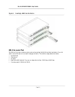
Page 10: ...D Link DES 3010FA GA Installation Guide Page 9 D Link DES 3010FA GA Installation Guide...

Page 11: ...Description This section contains a description of the D Link DES 3010FA and D Link DES 3010GA and contains the following topics Viewing the Device Ports Description Cable Specifications LED Defiitio...

Page 12: ...lustrates the DES 3010FA front panel Figure 1 DES 3010FA Front Panel The device front panel is configured as follows 8 Fast Ethernet ports RJ 45 ports designated as 10 100Base TX The RJ 45 ports are d...

Page 13: ...cal specification The port is used to connect the device to the console managing the device 1000Base T port RJ 45 Gigabit port designated on the device as port 9 SFP Port There is one SFP port which c...

Page 14: ...contains a 1000 Base TX Gigabit port The port is an RJ 45 port which supports half and full duplex mode 10 100 1000 Mbps 100Base FX Fiber Ports The 100Base FX Fast Ethernet port in the DES 3010FA devi...

Page 15: ...ial console port supporting the RS 232 electrical specification The port is used to connect the device to a console managing the device This interface configuration is as follows Eight data bits One s...

Page 16: ...dule 80km Mini GBIC SFP Transceiver for 1000BASE LX Single mode fiber module 10km SFP Transceiver for 1000BASE SX Multi mode fiber module 550m SFP Transceiver for 1000BASE LH Single mode fiber module...

Page 17: ...The RJ 45 ports have two LEDs one for speed and one for Link activity The LED indications are described in the following table 1000Base T Gigabit Ethernet RJ 45 Port LEDs The following figure illustr...

Page 18: ...er Port LEDs The following figure illustrates the port LEDs Table 4 1000Base T Gigabit Ethernet RJ 45 Port LED Indications Port Description LED Indication Description Left LED Speed Green A 100 1000 M...

Page 19: ...bed in the following table Table 5 Fiber Port LED Indications Port Description LED Indication Description Left LED Speed Green A 100 1000 Mbps link is established on the port Off No link is establishe...

Page 20: ...wing table Console LED The console status is indicated by the Console LED on the front panel of the device Table 6 SFP Port LED Indications Port Description LED Indication Description Left LED Speed G...

Page 21: ...e 10 100 1000 Ethernet Interface The switching port can connect to stations wired in standard RJ 45 Ethernet station mode using straight cables Transmission devices connected to each other use crossed...

Page 22: ...Device Description Physical Dimensions Page 21 Physical Dimensions The device has the following physical dimensions Width 220 mm 8 66 inch Depth 155mm 6 10 inch Height 35 mm 1 38 inch...

Page 23: ...e 22 Section 2 Mounting Device This section contains information for installing the device and includes the following sections Preparing for Installation Installing the Device Connecting the Device Ra...

Page 24: ...uching internal equipment Ensure the switch does not overload the power circuits wiring and over current protection To deter mine the possibility of overloading the supply circuits add together the am...

Page 25: ...S 232 cable with DB 9 connector Documentation CD Unpacking Essentials Note Before unpacking the device inspect the package and report any evidence of damage immediately To unpack the device perform th...

Page 26: ...d the device cables To install the device on a surface perform the following 1 Attach the rubber feet on the bottom of the device The following figure illustrates the rubber feet installation on the d...

Page 27: ...es on the device line up to the mounting holes on the rack mounting bracket The following figure illustrates where to mount the brackets Figure 11 Attaching the Mounting Brackets 2 Insert the supplied...

Page 28: ...n a Rack 5 Secure the unit to the rack with the rack screws not provided Fasten the lower pair of screws before the upper pair of screws This ensures that the weight of the unit is evenly distributed...

Page 29: ...made The hole diameter and depth is defined by the wall plug and screw combination being used to mount the device 3 Insert the wall plugs unto the holes 4 Screw the screws into the wall plugs allowing...

Page 30: ...l desktop system running terminal emulation software for monitoring and configuring the device The terminal must be a VT100 compatible terminal or a desktop or portable system with a serial port and r...

Page 31: ...2 the arrow keys function properly in HyperTerminal s VT100 emulation Go to www microsoft com for information on Windows 2000 service packs 3 Connect the cable to the console port on the device front...

Page 32: ...Starting and Configuring the Device This section describes initial device configuration and includes the following topics Configuring the Terminal Installation Procedure Booting the Device Configurati...

Page 33: ...HyperTerminal with Microsoft Windows 2000 make sure that Windows 2000 Service Pack 2 or later is installed With Windows 2000 Service Pack 2 the arrow keys function properly in HyperTerminal s VT100 em...

Page 34: ...oblem is detected the program flow stops If POST passes successfully a valid executable image is loaded into RAM POST messages are displayed on the terminal and indicate test success or failure As the...

Page 35: ...arts after the device has booted successfully includes static IP address and subnet mask configuration and setting user names and privilege levels to allow remote management If the device is to be man...

Page 36: ...e specific management station the IP address is defined on VLAN 1 and the default gateway is defined as 100 1 1 10 Note that by default all ports are members of VLAN 1 which is the default VLAN consol...

Page 37: ...nable console configure console config username admin password lee privilege 15 SNMP Community Strings Simple Network Management Protocol SNMP provides a method for managing network devices Devices su...

Page 38: ...ation During the initial configuration procedure the community string community access and IP address can be set through the local terminal The SNMP configuration options are Community string Read Onl...

Page 39: ...0FA GA User Guide Page 38 Contact System Location This completes the initial configuration of the device from a local terminal The configured parameters enable further device configuration from any re...

Page 40: ...ig interface ethernet 1 console config if ip address dhcp hostname admin host console config if exit console config 3 To verify the IP address enter the show ip interface command at the system prompt...

Page 41: ...ation Authorization and Accounting mechanism that manages user access rights privileges and management methods AAA uses both local and remote user databases Data encryption is handled through the SSH...

Page 42: ...To configure an initial Telnet password enter the following commands console config aaa authentication login default line console config aaa authentication enable default line console config line teln...

Page 43: ...in password user1 level 15 Enter the following commands when configuring to use a console a Telnet or an SSH session to use an HTTPS session In the Web browser enable SSL 2 0 or greater for the conten...

Page 44: ...continue y n n y SYSTEM RESET Performing the Power On Self Test POST UART Channel Loopback Test PASS Testing the System SDRAM PASS I2C Bus Test PASS Boot1 Checksum Test PASS Boot2 Checksum Test PASS...

Page 45: ...the Startup menu 1 From the Startup menu press 1 The following prompt appears Downloading code using XMODEM 2 When using HyperTerminal click Transfer on the HyperTerminal Menu Bar 3 In the Filename fi...

Page 46: ...the other system image copy On the next boot the device decompresses and runs the currently active system image unless otherwise directed To download a system image through the TFTP server 1 Ensure th...

Page 47: ...3 Enter show version to verify which software version is currently running on the device The following is an example of the information that appears console sh ver SW version 1 0 0 42 date 22 Jul 200...

Page 48: ...fied within 20 seconds the command times out To download a software image file using XModem 1 Enter the command console xmodem image The switch is ready to receive the file via the XModem protocol 2 S...

Page 49: ...D Link DES 3010FA GA User Guide Page 48 D Link DES 3010FA GA EWS User Guide...

Page 50: ...ction provides an introduction to the user interface and includes the following topics Starting the D Link Embedded Web Interface Understanding the D Link Embedded Web Interface Using Screen and Table...

Page 51: ...d device information messages may not open 3 Enter the device IP address in the address bar and press Enter The Enter Network Password Page opens Figure 15 Enter Network Password Page 4 Enter your use...

Page 52: ...g views Port LED Indicators Located at the top of the home page the port LED indicators provide a visual repre sentation of the ports on the D Link front panel Tab Area Located under the LED indicator...

Page 53: ...nents View Description 1 Tree View Tree View provides easy navigation through the configurable device features The main branches expand to display the sub features 2 Device View Device View provides i...

Page 54: ...icons provide an easy method of configuring device information and include the following Table 12 D Link Web Interface Configuration Buttons Button Button Name Description Clear Logs Clears system log...

Page 55: ...can be added to specific D Link Web Interface pages by opening a new Add page To add information to tables or D Link Web Interface pages 1 Open an D Link Web Interface page 2 Click An add page opens s...

Page 56: ...odify the fields as required 5 Click The fields are modified and the information is saved to the device Deleting Configuration Information 1 Open The D Link Embedded Web Interface page 2 Select a tabl...

Page 57: ...ent the current configuration from being lost save all changes from the running configuration file to the startup configuration file before resetting the device For instructions see Copying Files on p...

Page 58: ...Resetting the Device Page 57 Figure 22 Reset Confirmation Message 3 Click The device is reset and a prompt for a user name and password is displayed 4 Enter a user name and password to reconnect to th...

Page 59: ...D Link DES 3010FA GA User Guide Page 58 Logging off from the Device 1 Click The Logout Page opens Figure 23 Logout Page 2 Click The D Link Embedded Web Interface Home Page closes...

Page 60: ...ains the following fields Model Name Displays the device model number and name System Name Defines the user defined device name The field range is 0 160 characters System Location Defines the location...

Page 61: ...s the installed device hardware version number Software Version Displays the installed software version number Boot Version Displays the current boot version running on the device 2 Define the System...

Page 62: ...rity This section provides access to security pages that contain fields for setting security parameters for ports device management methods users and server security This section contains the followin...

Page 63: ...des the following topics Configuring Authentication Methods Configuring Passwords Configuring Authentication Methods This section provides information for configuring device authentication methods Thi...

Page 64: ...User Group 1 can access the switch module only via an HTTPS session while User Group 2 can access the switch module via both HTTPS and Telnet sessions The Access Profile Page contains the currently c...

Page 65: ...ule is defined Users with this access profile can access the device using the management method selected The possible field values are All Assigns all management methods to the rule Telnet Assigns Tel...

Page 66: ...on which the access profile is defined VLAN Specifies the VLAN on which the access profile is defined Source IP Address Defines the interface source IP address to which the access profile applies The...

Page 67: ...cri teria To define profile rules 1 Click System Management Security Authentication Profile Rules The Profile Rules Page opens Figure 27 Profile Rules Page The Profile Rules Page contains the followin...

Page 68: ...ing access profile criteria are permitted or denied access to the device Secure HTTP HTTPS Assigns HTTPS access to the rule If selected users accessing the device using HTTPS meeting access profile cr...

Page 69: ...hod Interface Source IP Address Network Mask or Prefix Length and Action fields 4 Click The profile rule is added to the access profile and the device is updated To modify a Profile Rule 1 Click Secur...

Page 70: ...Configuring Device Security Configuring Management Security Page 69 Figure 29 Profile Rule Settings Page 3 Modify the fields 4 Click The profile rule is modified and the device is updated...

Page 71: ...k System Management Security Authentication Authentication Profiles The Authentication Profile Page opens Figure 30 Authentication Profile Page The Authentication Profile Page contains the following f...

Page 72: ...n profiles 2 Click The Add Authentication Profile Page opens Figure 31 Add Authentication Profile Page 3 Define the Profile Name and Authentication Methods fields 4 Click The authentication profile is...

Page 73: ...010FA GA User Guide Page 72 Figure 32 Authentication Profile Settings Page 3 Select an authentication method from the Optional Methods list 4 Click The authentication method is selected and the device...

Page 74: ...Click System Management Security Authentication Authentication Mapping The Authentication Mapping Page opens Figure 33 Authentication Mapping Page The Authentication Mapping Page contains the followin...

Page 75: ...ed for access Local Authentication occurs locally RADIUS Authentication occurs at the RADIUS server Line Authentication using a line password Enable Authentication using enable Local RADIUS Authentica...

Page 76: ...the following fields Retries Defines the number of transmitted requests sent to the RADIUS server before a failure occurs Possible field values are 1 10 Timeout for Reply Defines the amount of time i...

Page 77: ...server before retrying the query or switching to the next server The possible field values are 1 30 Three is the default value Dead Time Defines the amount of time in minutes that a RADIUS server is b...

Page 78: ...e Host IP Address Priority Authenticated Port Timeout for Reply Dead Time and Usage Type fields 4 Click The RADIUS server is added and the device is updated To edit RADIUS Server Settings 1 Click Syst...

Page 79: ...e 78 Figure 36 RADIUS Server Settings Page 3 Define the Priority Source IP Address Key String Authentication Port Timeout for Reply Dead Time and Usage Type fields 4 Click The RADIUS server settings a...

Page 80: ...fine local users 1 Click System Management Security Passwords Local Users The Local User Page opens Figure 37 Local User Page The Local User Page contains the following fields User Name Displays the u...

Page 81: ...d Local User Page opens Figure 38 Add Local User Page In addition to the fields in the Local User Page the Add Local User Page contains the following fields Password Defines the local user password Lo...

Page 82: ...password for accessing the device via a Console session Pass words can contain a maximum of 159 characters Telnet Line Password Defines the line password for accessing the device via a Telnet session...

Page 83: ...ens Figure 40 Enable Password Page The Enable Password Page contains the following fields Level Defines the access level associated with the enable password Possible field values are 1 15 Password Def...

Page 84: ...access states Controlled Access Permits communication between the supplicant and the system if the supplicant is authorized Uncontrolled Access Permits uncontrolled communication regardless of the por...

Page 85: ...ation Properties The Network Authentication Properties Page allows network managers to configure network authentication parameters In addition Guest VLANs are enabled from the Network Authentication P...

Page 86: ...the session is permitted Guest VLAN Specifies whether the Guest VLAN is enabled on the device The possible field values are Enable Enables using a Guest VLAN for unauthorized ports If a Guest VLAN is...

Page 87: ...interfaces on which port based authentication is enabled User Name Displays the supplicant user name Admin Port Control Displays the current port authorization state The possible field values are Aut...

Page 88: ...et state following a failed authentication exchange The possible field range is 0 65535 The field default is 60 seconds Resending EAP Defines the amount of time in seconds that lapses before EAP reque...

Page 89: ...Port Authentication Settings Page 3 Modify the Admin Port Control Enable Periodic Reauthentication Quiet Period Resending EAP Supplicant Timeout and Server Timeout fields 4 Click The port authenticati...

Page 90: ...rt Displays the port number for which advanced port based authentication is enabled Multiple Hosts Indicates whether multiple hosts are enabled Multiple hosts must be enabled in order to either disabl...

Page 91: ...e Unauthorized and the port link is down or the port control is Auto but a client has not been authenticated via the port Not in Auto Mode Indicates that the port control is Forced Authorized and clie...

Page 92: ...he following fields User Name Lists the supplicants that were authenticated and are permitted on each port Port Displays the port number Session Time Displays the amount of time in seconds the supplic...

Page 93: ...o users with specific MAC addresses These addresses are either manually defined on the port or learned on that port up to the point when it is locked When a packet is received on a locked port and the...

Page 94: ...the port control is Auto and a single client has been authenticated via the port Learning Mode Defines the locked port type The Learning Mode field is enabled only if Locked is selected in the Set Po...

Page 95: ...The port remains shut down until reactivated or until the device is reset Trap Enables traps when a packet is received on a locked port The possible field values are Checked Enables traps Unchecked Di...

Page 96: ...is enabled for all Gigabit ports by defining the packet type and the rate the packets are transmitted The system measures the incoming Broadcast and Multicast frame rates separately on each port and...

Page 97: ...affic Broadcast Rate Threshold The maximum rate kilobytes per second at which unknown packets are for warded The range is 0 1 000 000 The default value is zero All values are rounded to the nearest 64...

Page 98: ...nfiguration LAG table The Interface Configuration ports table contains the following fields Interface Displays the port number Port Status Indicates whether the port is currently operational or non op...

Page 99: ...status on the port Operates when the port is in full duplex mode MDI MDIX Displays the MDI MDIX status on the port Hubs and switches are deliberately wired opposite the way end stations are wired so t...

Page 100: ...ort or LAG Configuration Settings Page includes the field Reactivate Suspended Port or Reactivate Suspended Lag Select this field to return a suspended port or LAG to active status Figure 52 Port Conf...

Page 101: ...The Interface Properties Page is contains the following fields Interface Displays the port number Port Type Displays the port type The possible field values are Copper Indicates the port has a copper...

Page 102: ...Configuring Ports Viewing Port Properties Page 101 Figure 54 Interface Properties Page 3 Define the fields 4 Click The interface properties are modified and the device is updated...

Page 103: ...egotiation mode is not configured on the port The port is in full duplex mode All ports in the LAG have the same ingress filtering and tagged modes All ports in the LAG have the same back pressure and...

Page 104: ...he device supports up to eight ports per LAG and eight LAGs per system To define LAG parameters 1 Click Advanced Setup Interface LAG Membership The LAG Membership Page opens Figure 55 LAG Membership P...

Page 105: ...D Link DES 3010FA GA User Guide Page 104 Figure 56 LAG Membership Settings Page 3 Define the Port and LACP fields 4 Click The LAG membership settings are saved and the device is updated...

Page 106: ...gate ports can be linked into link aggregation port groups Each group is comprised of ports with the same speed The LACP Parameters Page contains fields for configuring LACP LAGs To configure LACP for...

Page 107: ...D Link DES 3010FA GA User Guide Page 106 Figure 58 LACP Parameters Settings Page 3 Edit the Port Priority and LACP Timeout fields 4 Click The LACP settings are saved and the device is updated...

Page 108: ...r working at a protocol level is required to allow traffic flow between VLANs Layer 3 routers identify segments and coordinate with VLANs VLANs are Broadcast and Multicast domains Broadcast and Multic...

Page 109: ...D Displays the VLAN ID Name Displays the user defined VLAN name Type Displays the VLAN type The possible field values are Dynamic The VLAN was dynamically created through GARP Static The VLAN is user...

Page 110: ...figuring VLANs Defining VLAN Properties Page 109 2 Click The Add VLAN page opens Figure 60 Add VLAN Page 3 Define the VLAN ID and VLAN Name fields 4 Click The VLAN ID is defined and the device is upda...

Page 111: ...he user defined VLAN ID VLAN Name Displays the name of the VLAN VLAN Type Indicates the VLAN type The possible field values are Dynamic The VLAN was dynamically created through GARP Static The VLAN is...

Page 112: ...1 Click Basic Setup VLAN Membership Interface Settings The VLAN Interface Settings Page opens Figure 62 VLAN Interface Settings Page The VLAN Interface Settings Page contains the following fields Int...

Page 113: ...nly Only tagged packets are accepted on the port Admit All Both tagged and untagged packets are accepted on the port Ingress Filtering Indicates whether ingress filtering is enabled on the port The po...

Page 114: ...with a VLANs is blocked except for traffic from promiscuous ports All isolated ports are automatically assigned to the Iso lated VLAN Community Community ports communicate with other community ports a...

Page 115: ...e VLANs are defined in the Add Private VLAN page Isolated Ports Indicates which VLAN to which isolated ports are assigned Community Ports Adds a Community VLAN to which community ports are assigned Re...

Page 116: ...LANs Defining Private VLANs Page 115 Figure 65 Add Private VLAN 3 Define the New Private VLAN and Community VLAN 2 4093 or Isolated VLAN 2 4093 fields 4 Click The Private VLAN is created and the devic...

Page 117: ...e time must be greater than or equal to three times the join time The leave all time must be greater than the leave time Set the same GARP timer values on all Layer 2 connected devices If the GARP tim...

Page 118: ...Leave time must be greater than or equal to three times the join time The default value is 60 centiseconds Leave All Timer Indicates the amount of time lapse in centiseconds that all device waits befo...

Page 119: ...definitions are the same The GVRP Parameters Page contains the following fields GVRP Global Status Indicates if GVRP is enabled on the device The possible field values are Enable Enables GVRP on the...

Page 120: ...n on the interface GVRP Registration Indicates if VLAN registration through GVRP is enabled on the device The possible field values are Enable Enables GVRP registration on the device Disable Disables...

Page 121: ...ning device IP addresses and includes the following topics Configuring IP Interfaces Configuring Domain Name Servers Configuring IP Interfaces This section contains information for defining IP interfa...

Page 122: ...interface 1 Click Basic Setup IP Configuration IP Addressing IP Interface The IP Interface Page opens Figure 70 IP Interface Page The IP Interface Page contains the following fields IP Address Display...

Page 123: ...or Prefix Length and Interface fields 4 Click The IP configuration fields are saved and the device is updated To modify an IP interface 1 Click Basic Setup IP Configuration IP Addressing IP Interface...

Page 124: ...Configuring IP Information Configuring IP Interfaces Page 123 3 Modify the IP Address Network Mask or Prefix Length and Interface fields 4 Click The IP Interface is modified and the device is updated...

Page 125: ...tains the following fields User Defined Default Gateway Defines the default gateway IP address Active Default Gateway Indicates if the default gateway is active The possible field values are Checked A...

Page 126: ...etwork To define a DHCP Interface 1 Click Basic Setup IP Configuration IP Addressing DHCP The DCHP Page opens Figure 74 DCHP Page The DCHP Page contains the following fields Interface Displays the int...

Page 127: ...D Link DES 3010FA GA User Guide Page 126 Figure 75 Add DHCP IP Interface Page 3 Define the Interface and Host Name fields 4 Click The DHCP interface is added and the device is updated...

Page 128: ...amount of time in seconds that passes between ARP Table entry requests Following the ARP Entry Age period the entry is deleted from the table The range is 1 40000000 The default value is 60000 seconds...

Page 129: ...a static entry Remove Removes a specific ARP entry The possible field values are Checked Removes the selected ARP entries Unchecked Maintains the current ARP entries 2 Define the ARP Entry Age Out and...

Page 130: ...mes into IP addresses Each time a domain name is assigned the DNS service translates the name into a numeric IP address For example www ipexample com is translated into 192 87 56 2 DNS servers maintai...

Page 131: ...Enable Translates the domains into IP addresses Disable Disables translating domains into IP addresses Default Domain Name Specifies the user defined DNS server name Type Displays the IP address type...

Page 132: ...ctive Server fields 4 Click The DNS server is enabled and the device is updated To add a new DNS Server 1 Click Basic Setup IP Configuration Domain Name System DNS Server The DNS Server Page opens 2 C...

Page 133: ...Mapping Page The DNS Host Mapping Page contains the following fields Host Names Displays a user defined default domain name When defined the default domain name is applied to all unqualified host name...

Page 134: ...Configuring IP Information Configuring Domain Name Servers Page 133 Figure 81 Add DNS Host Page 3 Define the Host Name and IP Address fields 4 Click The DNS host is added and the device is updated...

Page 135: ...nfig ured manually An address becomes associated with a port by learning the port from the frame s source address but if a frame that is addressed to a destination MAC address is not associated with a...

Page 136: ...ng Database Static Addresses Page The Forwarding Database Static Addresses Page contains the following fields MAC Address Displays the MAC address to which the entry refers VLAN ID Displays the VLAN I...

Page 137: ...eset make sure that the port attached to the MAC address is locked To add a new static forwarding database entry 1 Click Advanced Setup Forwarding Database Static Addresses The Forwarding Database Sta...

Page 138: ...rface VLAN and MAC Address To configure the Dynamic MAC Address table 1 Click Advanced Setup Forwarding Database Dynamic Addresses The Dynamic Addresses Page opens Figure 84 Dynamic Addresses Page The...

Page 139: ...and the device is updated To query the Dynamic MAC Address Table 1 Click Advanced Setup Forwarding Database Dynamic Addresses The Dynamic Addresses Page opens 2 Select a port MAC Address and VLAN ID 3...

Page 140: ...and eliminating loops For more infor mation on configuring Classic STP see Defining Classic Spanning Tree Rapid STP Detects and uses network topologies that provide faster convergence of the spanning...

Page 141: ...pecifies the STP mode that is enabled on the device The possible field values are Classic STP Enables Classic STP on the device This is the default value Rapid STP Enables Rapid STP on the device Mult...

Page 142: ...lay 4 30 Specifies the device Forward Delay Time The Forward Delay Time is the amount of time in seconds a bridge remains in a listening and learning state before forwarding packets The default is 10...

Page 143: ...ndicates that STP is disabled on the port Fast Link Indicates if Fast Link is enabled on the port If Fast Link mode is enabled for a port the Port State is automatically placed in the Forwarding state...

Page 144: ...The priority value is determined in increments of 16 Designated Bridge ID Indicates the bridge priority and the MAC Address of the designated bridge Designated Port ID Indicates the selected port D Li...

Page 145: ...D Link DES 3010FA GA User Guide Page 144 4 Define the Fast Link Enable Root Guard Path Cost Default Path Cost and Priority fields 5 Click STP is enabled on the interface and the device is updated...

Page 146: ...Tree RSTP RSTP The RSTP Page opens Figure 88 RSTP Page The RSTP Page contains the following fields Interface Displays the port or LAG on which Rapid STP is enabled Role Displays the port role assigned...

Page 147: ...gured to automatically establish a point to point link To establish communications over a point to point link the originating PPP first sends Link Control Protocol LCP packets to configure and test th...

Page 148: ...Defining Rapid Spanning Tree Page 147 Figure 89 RSTP Settings Page 3 Define the Interface Point to Point Admin Status and Activate Protocol Migration fields 4 Click RSTP is defined for the interface...

Page 149: ...number that identifies the revision of the current MSTP configuration The revision number is required as part of the MSTP configuration The possible field range is 0 65535 Max Hops Specifies the tota...

Page 150: ...STP Instance Settings Page contains the following fields Instance ID Specifies the VLAN group to which the interface is assigned Included VLAN Maps the selected VLANs to the selected instance Each VLA...

Page 151: ...D Link DES 3010FA GA User Guide Page 150 Figure 92 VLAN Instance Configuration Table 3 Define the Instance ID field 4 Click The MSTP Instances are assigned and the device is updated...

Page 152: ...onfigured on the device Possible field range is 0 15 Interface Displays the interface for which the MSTP settings are displayed The possible field values are Port Specifies the port for which the MSTP...

Page 153: ...by a point to point link or when a LAN has two or more connections connected to a shared segment Disabled Indicates the port is not participating in the Spanning Tree Mode Indicates the STP mode by wh...

Page 154: ...Spanning Tree Defining Multiple Spanning Tree Page 153 Figure 94 MSTP Interface Table 3 Define the Port Priority and the Path Cost fields 4 Click The MSTP interface settings are defined and the device...

Page 155: ...10FA GA User Guide Page 154 Section 13 Configuring Multicast Forwarding This section contains the following topics Defining IGMP Snooping Defining Multicast Bridging Groups Defining Multicast Forward...

Page 156: ...s This results in the creation of the Multicast filtering database To enable IGMP Snooping 1 Click Multicast Support IGMP The IGMP Snooping Page opens Figure 95 IGMP Snooping Page The IGMP Snooping Pa...

Page 157: ...sage before it times out The default value is 300 seconds Leave Timeout Indicates the amount of time the host waits after requesting to leave the IGMP group and not receiving a Join message from anoth...

Page 158: ...icast groups 1 Click Advanced Setup Multicast Support Bridge Multicast Multicast Group The Multicast Group Page opens Figure 97 Multicast Group Page The Multicast Group Page contains the following inf...

Page 159: ...ort settings 6 Click The Multicast group is defined and the device is updated Table 14 IGMP Port LAG Members Table Control Settings Port Control Definition D Dynamically joins ports LAG to the Multica...

Page 160: ...nced Setup Multicast Support Bridge Multicast Multicast Forward All The Multicast Forward All Page opens Figure 99 Multicast Forward All Page The Multicast Forward All Page contains the following fiel...

Page 161: ...3 Define the VLAN port settings 4 Click The Multicast forward all settings are defined and the device is updated F Forbidden Blank The port is not attached to a Multicast router or switch Table 15 Br...

Page 162: ...or SNMPv3 including Authentication Provides data integrity and data origin authentication Privacy Protects against the disclosure of message content Cipher Block Chaining CBC is used for encryption Ei...

Page 163: ...ications To define the SNMP security parameters 1 Click System SNMP Security Global Parameters The SNMP Security Global Parameters Page opens Figure 100 SNMP Security Global Parameters Page The SNMP S...

Page 164: ...ice MAC address and is defined per standard as First 4 octets first bit 1 the rest is IANA Enterprise number Fifth octet Set to 3 to indicate the MAC address that follows Last 6 octets MAC address of...

Page 165: ...The SNMP Security Views Page opens Figure 101 SNMP Security Views Page The SNMP Security Views Page contains the following fields View Name Displays the user defined views The view name can contain a...

Page 166: ...SNMP Configuring SNMP Security Page 165 Figure 102 Add SNMP View Page 3 Define the View Name field 4 Define the view using and 5 Define the View Type field 6 Click The view is defined and the device...

Page 167: ...The SNMP Group Profile Page contains the following fields Group Name Displays the user defined group to which access control rules are applied The field range is up to 30 characters Security Model De...

Page 168: ...nges can be made to the assigned SNMP view Notify Sends traps for the assigned SNMP view Remove Removes SNMP groups The possible field values are Checked Removes the selected SNMP group Unchecked Main...

Page 169: ...0FA GA User Guide Page 168 Figure 105 SNMP Group Profile Settings Page 3 Modify the Group Name Security Model Security Level and Operation fields 4 Click The SNMP group profile is modified and the dev...

Page 170: ...ngine ID Displays either the local or remote SNMP entity to which the user is connected Changing or removing the local SNMP Engine ID deletes the SNMPv3 user database Local Indicates that the user is...

Page 171: ...16 bytes are defined If both privacy and authentication are required 32 bytes are defined Each byte in hexadecimal character strings is two hexadecimal digits Each byte can be separated by a period or...

Page 172: ...ity Page 171 Figure 108 SNMP Group Membership Settings Page 3 Modify the Group Name Engine ID Authentication Method Password Authentication Key and Privacy Key fields 4 Click The SNMP group membership...

Page 173: ...the following tables Basic Table Advanced Table SNMP Communities Basic Table The SNMP Communities Basic Table contains the following fields Management Station Displays the management station IP addres...

Page 174: ...which the advanced SNMP com munity is defined Community String Defines the password used to authenticate the management station to the device Group Name Defines advanced SNMP community group names Rem...

Page 175: ...0FA GA User Guide Page 174 Figure 111 SNMP Community Settings Page 3 Modify the SNMP Management Station Community String and Basic or Advanced fields 4 Click The SNMP community is modified and the dev...

Page 176: ...75 Configuring SNMP Notifications This section contains information for configuring SNMP Notifications and contains the following topics Defining SNMP Notification Global Parameters Defining SNMP Noti...

Page 177: ...SNMP Notifications Specifies whether the device can send SNMP notifications The possible field values are Enable Enables SNMP notifications Disable Disables SNMP notifications Enable Authentication N...

Page 178: ...he SNMP Notification Filter Page contains the following fields Filter Name Contains a list of user defined notification filters Object ID Subtree Displays the OID for which notifications are sent or b...

Page 179: ...GA User Guide Page 178 Figure 114 Add SNMP Notification Filter Page 3 Define the Filter Name New Object Identifier Tree and Filter Type fields 4 Click The SNMP notification filter is defined and the...

Page 180: ...filters provide the following services Identifying Management Trap Targets Trap Filtering Selecting Trap Generation Parameters Providing Access Control Checks To define SNMP notification filters 1 Cli...

Page 181: ...ues are SNMP V1 Indicates that SNMP Version 1 traps are sent SNMP V2c Indicates that SNMP Version 2 traps are sent UDP Port Displays the UDP port used to send notifications The default is 162 Filter N...

Page 182: ...that the packet is neither authenticated nor encrypted Authentication Indicates that the packet is authenticated UDP Port The UDP port used to send notifications The field range is 1 65535 The default...

Page 183: ...ted To modify SNMP notification recipients 1 Click System SNMP Notification Notification Receiver The SNMP Notification Receiver Page opens 2 Click The SNMP Notification Receiver Settings Page opens F...

Page 184: ...et field values such as VLAN Priority Tag VPT and DiffServ Code Point DSCP VPT Classification Information VLAN Priority Tags VPT are used to classify packets by mapping packets to one of the egress qu...

Page 185: ...before FTP or e mail SMTP traffic Weighted Round Robin Ensures that a single application does not dominate the device forwarding capacity Weighted Round Robin WRR forwards entire queues in a round rob...

Page 186: ...eneral Settings Page contains fields for enabling or disabling CoS In addition the Trust mode can be selected The Trust mode relies on predefined fields within the packet to determine the egress queue...

Page 187: ...field is mapped according to the relevant trust modes table Traffic not containing a predefined packet field is mapped to best effort The possible Trust Mode field values are CoS Classifies traffic ba...

Page 188: ...Figure 119 Bandwidth Settings Page The Bandwidth Settings Page displays the following fields Status Indicates if rate limiting is enabled on the interface The possible field values are Enable Indicat...

Page 189: ...Interface Page contains the following fields Interface The port or LAG for which the default CoS policy is defined Trust Mode Indicates whether or not Trust Mode is enabled on the interface The possi...

Page 190: ...ice Defining Bandwidth Settings Page 189 Figure 121 Edit Interface Settings Page 3 Define the Disable Trust Mode Default CoS and Restore Defaults fields 4 Click The QoS Interface settings are modified...

Page 191: ...tains the following fields Strict Priority Specifies whether traffic scheduling is based strictly on the queue priority WRR Assigns WRR weights to queues This field is enabled only for queues in WRR q...

Page 192: ...Queue Mapping CoS to Queue The CoS to Queue Page opens Figure 123 CoS to Queue Page The CoS to Queue Page contains the following fields Class of Service Specifies the CoS priority tag values where zer...

Page 193: ...ality of Service Queue Mapping DSCP to Queue The DSCP to Queue Page opens Figure 124 DSCP to Queue Page The DSCP to Queue Page contains the following fields DSCP In Displays the incoming packet s DSCP...

Page 194: ...6 Managing System Files File maintenance includes both configuration file management as well as device access This section contains the following topics File Management Overview Downloading System Fil...

Page 195: ...the Run ning Configuration file are lost During the startup process all commands in the Startup file are copied to the Running Configuration File and applied to the device During the session all new...

Page 196: ...ge The File Download Page is divided into the following sections Firmware Download Configuration Download Firmware Download The Firmware Download section contains the following fields Firmware Downloa...

Page 197: ...ess Specifies the TFTP Server IP Address from which the configuration files are downloaded Source File Name Specifies the configuration files to be downloaded Destination File Specifies the destinatio...

Page 198: ...le Upload Page The File Upload Page is divided into the following sections Software Image Upload Configuration Upload Upload Type The Upload Type section contains the following fields Firmware Upload...

Page 199: ...llowing fields TFTP Server IP Address Specifies the TFTP Server IP Address to which the Configuration file is uploaded Destination File Name Specifies the file name to which the Startup Configuration...

Page 200: ...ning Configuration file is selected Destination Indicates the Startup Configuration file is selected Restore Configuration Factory Defaults Resets the Configuration file to the factory defaults The fa...

Page 201: ...based on their urgency or relevancy Each message severity determines the set of event logging devices that are sent per each event message The following table lists the log severity levels This sectio...

Page 202: ...The possible field values are Checked Enables device logs Unchecked Disables device logs Severity The following are the available log severity levels Emergency The highest warning level If the device...

Page 203: ...n are selected automatically Console Defines the minimum severity level from which logs are sent to the console RAM Logs Defines the minimum severity level from which logs are sent to the RAM Log kept...

Page 204: ...Page opens Figure 129 Device Memory Log Page The Device Memory Log Pagecontains the following fields Log Index Displays the log number Log Time Displays the time at which the log was generated Severi...

Page 205: ...he message logs Click System Syslog Flash The Syslog Flash Page opens Figure 130 Syslog FLASH Page The Syslog Flash Page contains the following fields Log Index Displays the log number Log Time Displa...

Page 206: ...are sent to the remote server Only one facility can be assigned to a single server If a second facility level is assigned the first facility is overridden All applica tions defined for a device utiliz...

Page 207: ...A User Guide Page 206 Section 18 Managing Device Diagnostics This section contains the following topics Configuring Port Mirroring Viewing Integrated Cable Tests Viewing Optical Transceivers Viewing t...

Page 208: ...opens Figure 132 Port Mirroring Page The Port Mirroring Page contains the following fields Destination Port Defines the port number to which port traffic is copied Transmit Packets Defines the how th...

Page 209: ...ick The Add Port Mirroring Page opens Figure 133 Add Port Mirroring Page 3 Select a port in the Source Port field 4 Select a port type in the Type field 5 Click The port mirroring session is defined a...

Page 210: ...o test cables 1 Click System Diagnostics Copper Cable The Cable Tests Page opens Figure 135 Cable Tests Page The Cable Tests Page contains the following fields Port Specifies the port to which the cab...

Page 211: ...ins the field Port Displays the port IP address on which the cable is tested Temperature Displays the temperature C at which the cable is operating Voltage Displays the voltage at which the cable is o...

Page 212: ...n Click System Diagnostics CPU Utilization The CPU Utilization Page opens Figure 137 CPU Utilization Page The CPU Utilization Page contains the following fields Refresh Rate Amount of time that passes...

Page 213: ...k DES 3010FA GA User Guide Page 212 Section 19 Configuring System Time This section provides information for configuring system time parameters including Configuring Daylight Savings Time Configuring...

Page 214: ...first Sunday in April until the last Sunday of October Daylight Saving Time is usually regulated by provincial and territorial governments Exceptions may exist in certain municipalities Cuba From the...

Page 215: ...last weekend of October Russia From the last weekend of March until the last weekend of October Serbia From the last weekend of March until the last weekend of October Slovak Republic From the last w...

Page 216: ...the device s location There are two types of daylight settings either by a specific date in a particular year or a recurring setting irrespective of the year For a specific setting in a particular yea...

Page 217: ...and Europe From The time that DST begins each year In the example DST begins locally every first Sunday in April at midnight The possible field values are Day The day of the week from which DST begins...

Page 218: ...d by the following time levels T1 The time at which the original request was sent by the client T2 The time at which the original request was received by the server T3 The time at which the server sen...

Page 219: ...D Link DES 3010FA GA User Guide Page 218 This section contains the following topics Defining SNTP Global Settings Defining SNTP Authentication Defining SNTP Servers Defining SNTP Interface Settings...

Page 220: ...the selected interfaces The possible values are Enable Enables the device to receive Broadcast server updates Disable Disables the device from receiving Broadcast server updates Enable Receive Anycas...

Page 221: ...Servers Defines whether or not the device sends SNTP Unicast forwarding informa tion to the SNTP server The possible values are Enable Enables the device to receive Poll Unicast server updates Disable...

Page 222: ...icates SNTP sessions between the device and SNTP server Unchecked Disables authenticating SNTP sessions between the device and SNTP server Encryption Key ID Indicates if the encryption key identificat...

Page 223: ...P authentication parameters 1 Click The Add SNTP Authentication page opens Figure 141 Add SNTP Authentication 2 Define the Encryption Key ID Authentication Key and Trusted Key fields 3 Click The SNTP...

Page 224: ...icates whether or not the device polls the selected SNTP server for system time informa tion Encryption Key ID Displays the encryption key identification used to communicate between the SNTP server an...

Page 225: ...er Guide Page 224 2 Click The Add SNTP Server Page opens Figure 143 Add SNTP Server Page 3 Define the SNTP Server Enable Poll Interval and Encryption Key ID fields 4 Click The SNTP Server is added and...

Page 226: ...gs Page contains the following fields Interface Indicates the interface on which SNTP can be enabled The possible field values are Port Indicates the specific port number on which SNTP is enabled LAG...

Page 227: ...D Link DES 3010FA GA User Guide Page 226 Figure 145 Add SNTP Interface Page 3 Define the Interface and Receive Server Updates fields 4 Click The SNTP interface is added and the device is updated...

Page 228: ...RMON interfaces GVRP EAP and Etherlike statistics This section contains the following topics Viewing Interface Statistics Managing RMON Statistics Viewing Interface Statistics This section contains th...

Page 229: ...before the interface statistics are refreshed The possible field values are 15 Sec Indicates that the Interface statistics are refreshed every 15 seconds 30 Sec Indicates that the Interface statistics...

Page 230: ...number of Broadcast packets transmitted from the selected interface 2 Select an interface in the Interface field The interface statistics are displayed Resetting Interface Statistics Counters 1 Open...

Page 231: ...terface Single Collision Frames Displays the number of single collision frames received on the selected interface Late Collisions Displays the number of late collision frames received on the selected...

Page 232: ...es the amount of time that passes before the GVRP statistics are refreshed The pos sible field values are 15 Sec Indicates that the GVRP statistics are refreshed every 15 seconds 30 Sec Indicates that...

Page 233: ...statistics counters are cleared Viewing EAP Statistics The EAP Statistics Page contains information about EAP packets received on a specific port To view the EAP Statistics Click Advanced Setup Inter...

Page 234: ...t Request ID Frames Transmit Indicates the number of EAP Req Id frames transmitted via the port Request Frames Transmit Indicates the number of EAP Request frames transmitted via the port Invalid Fram...

Page 235: ...resh Rate Defines the amount of time that passes before the interface statistics are refreshed The possible field values are 15 Sec Indicates that the RMON statistics are refreshed every 15 seconds 30...

Page 236: ...last refreshed Fragments Displays the number of fragments packets with less than 64 octets excluding framing bits but including FCS octets received on the interface since the device was last refreshed...

Page 237: ...gure 151 RMON History Control Page The RMON History Control Page contains the following fields History Entry No Displays the entry number for the History Control Table page Source Interface Displays t...

Page 238: ...ves History Control entries The possible field values are Checked Removes the selected History Control entry Unchecked Maintains the current History Control entries 2 Click The RMON History Control Se...

Page 239: ...umber Indicates the sample number from which the statistics were taken Drop Events Displays the number of dropped events that have occurred on the interface since the device was last refreshed Receive...

Page 240: ...f undersized packets less than 64 octets received on the interface since the device was last refreshed Oversize Packets Displays the number of oversized packets over 1518 octets received on the interf...

Page 241: ...lisions Displays the number of collisions received on the interface since the device was last refreshed Utilization Displays the percentage of the interface utilized 2 Select an entry in the History E...

Page 242: ...scribes the event type Possible values are Log Indicates that the event is a log entry Trap Indicates that the event is a trap Log and Trap Indicates that the event is both a log entry and a trap None...

Page 243: ...Click Advanced Setup RMON Events Events Logs The RMON Events Logs Page opens Figure 155 RMON Events Logs Page The RMON Events Logs Page contains the following fields Event Displays the RMON Events Lo...

Page 244: ...ed value from the current value The difference in the values is compared to the threshold Absolute Compares the values directly with the thresholds at the end of the sampling interval Rising Threshold...

Page 245: ...rval Defines the alarm interval time in seconds Owner Displays the device or user that defined the alarm Remove Removes the RMON Alarms Table entry 2 Click The RMON Alarms Definition Page opens Figure...

Page 246: ...e when installing the and how to resolve these issue This section includes the following topics Problem Management Provides information about problem management with DES 3010FA GA Troubleshooting Solu...

Page 247: ...open Lost password Problems Possible Cause Solution Cannot connect to man agement using RS 232 serial connection Be sure the terminal emulator program is set to VT 100 compatible 9600 baud rate no par...

Page 248: ...ion with IP protocol Replace the cable Replace the module Replace the module Erase the connection and reconfigure the port Device is in a reboot loop Software fault Download and install a working or p...

Page 249: ...message is displayed Console reload Are you sure you want to reboot the system y n n 2 Enter Y The device reboots After the POST when the text Autoboot in 2 seconds press RETURN or Esc to abort and en...

Page 250: ...ware updates and user documentation can be found on the D Link website D Link provides free technical support for customers within the United States and within Canada for the warranty duration For mor...

Page 251: ...D Link DES 3010FA GA User Guide Page 250...

Page 252: ...Contacting D Link Technical Support Page 251...

Page 253: ...D Link DES 3010FA GA User Guide Page 252...

Page 254: ...Contacting D Link Technical Support Page 253...

Page 255: ...D Link DES 3010FA GA User Guide Page 254...

Page 256: ...Contacting D Link Technical Support Page 255...

Page 257: ...D Link DES 3010FA GA User Guide Page 256...

Page 258: ...Contacting D Link Technical Support Page 257...

Page 259: ...D Link DES 3010FA GA User Guide Page 258...

Page 260: ...Contacting D Link Technical Support Page 259...

Page 261: ...D Link DES 3010FA GA User Guide Page 260...

Page 262: ...Contacting D Link Technical Support Page 261...

Page 263: ...D Link DES 3010FA GA User Guide Page 262...

Page 264: ...Contacting D Link Technical Support Page 263...

Page 265: ...D Link DES 3010FA GA User Guide Page 264...

Page 266: ...Contacting D Link Technical Support Page 265...

Page 267: ...D Link DES 3010FA GA User Guide Page 266...

Page 268: ...Contacting D Link Technical Support Page 267...

Page 269: ...D Link DES 3010FA GA User Guide Page 268...

Page 270: ...Contacting D Link Technical Support Page 269...

Page 271: ...D Link DES 3010FA GA User Guide Page 270...

Page 272: ...Contacting D Link Technical Support Page 271...

Page 273: ...D Link DES 3010FA GA User Guide Page 272...

Page 274: ...Contacting D Link Technical Support Page 273...

Page 275: ...D Link DES 3010FA GA User Guide Page 274...

Page 276: ...Contacting D Link Technical Support Page 275...

Page 277: ...rdware will be refunded by D Link upon return to D Link of the defective Hardware All Hardware or part thereof that is replaced by D Link or for which the purchase price is refunded shall become the p...

Page 278: ...be prepaid by D Link if you use an address in the United States otherwise we will ship the product to you freight collect Expedited shipping is available upon request and provided shipping charges ar...

Page 279: ...stered trademarks are the property of their respective owners Copyright Statement No part of this publication or documentation accompanying this product may be reproduced in any form or by any means o...

Page 280: ...279 Product Registration D Link products can be registered online at http support dlink com register Product registration is entirely voluntary and failure to complete or return this form will not dim...

Page 281: ...fnock Avenue North Ryde NSW 2113 Australia TEL 61 2 8899 1800 FAX 61 2 8899 1868 URL www dlink com au India D Link House Kurla Bandra Complex Road Off CST Road Santacruz East Mumbai 400098 India TEL 9...

Reviews: