background image

DES-3028 DES-3028P DES-3028G DES-3052 DES-3052P Layer 2 Fast Ethernet Managed Switch 

This protocol will also tag BPDU packets so receiving devices can distinguish spanning tree instances, spanning tree regions and 
the VLANs associated with them. An MSTI ID will classify these instances. MSTP will connect multiple spanning trees with a 
Common and Internal Spanning Tree (CIST). The CIST will automatically determine each MSTP region, its maximum possible 
extent and will appear as one virtual bridge that runs a single spanning tree. Consequentially, frames assigned to different VLANs 
will follow different data routes within administratively established regions on the network, continuing to allow simple and full 
processing of frames, regardless of administrative errors in defining VLANs and their respective spanning trees. 

Each switch utilizing the MSTP on a network will have a single MSTP configuration that will have the following three attributes: 

1.


A configuration name defined by an alphanumeric string of up to 32 characters (defined in the 

STP Bridge Global 

Settings 

window in the Configuration Name


field). 

2.


A configuration revision number (named here as a Revision Level and found in the 

STP Bridge Global Settings 

window) 

and; 

3.


A 4096-element table (defined here as a VID List in the 

MST Configuration Table

 window), which will associate each 

of the possible 4096, VLANs supported by the Switch for a given instance. 

 To utilize the MSTP function on the Switch, three steps need to be taken: 

1.


The Switch must be set to the MSTP setting (found in the

 STP Bridge Global Settings

 window in the STP Version field) 

2.


The correct spanning tree priority for the MSTP instance must be entered (defined here as a Priority in the 

MST 

Configuration Table

 window when configuring an MSTI ID


settings). 

3.


VLANs that will be shared must be added to the MSTP Instance ID (defined here as a


VID List


in the

 MST 

Configuration


Table

 window when configuring an MSTI ID settings). 

802.1w Rapid Spanning Tree 

The Switch implements two versions of the Spanning Tree Protocol, the Rapid Spanning Tree Protocol (RSTP) as defined by the 
IEEE 802.1w specification and a version compatible with the IEEE 802.1d STP. RSTP can operate with legacy equipment 
implementing IEEE 802.1d, however the advantages of using RSTP will be lost.   

The IEEE 802.1w Rapid Spanning Tree Protocol (RSTP) evolved from the 802.1d STP standard. RSTP was developed in order to 
overcome some limitations of STP that impede the function of some recent switching innovations, in particular, certain Layer 3 
functions that are increasingly handled by Ethernet switches. The basic function and much of the terminology is the same as STP. 
Most of the settings configured for STP are also used for RSTP. This section introduces some new Spanning Tree concepts and 
illustrates the main differences between the two protocols.  

Port Transition States 

An essential difference between the three protocols is in the way ports transition to a forwarding state and in the way this 
transition relates to the role of the port (forwarding or not forwarding) in the topology. RSTP combines the transition states 
disabled, blocking and listening used in 802.1d and creates a single state Discarding. In either case, ports do not forward packets. 
In the STP port transition states disabled, blocking or listening or in the RSTP port state discarding, there is no functional 
difference, the port is not active in the network topology. Table 6-2 below compares how the two protocols differ regarding the 
port state transition. 

All three protocols calculate a stable topology in the same way. Every segment will have a single path to the root bridge. All 
bridges listen for BPDU packets. However, BPDU packets are sent more frequently - with every Hello packet. BPDU packets are 
sent even if a BPDU packet was not received. Therefore, each link between bridges is sensitive to the status of the link. Ultimately 
this difference results in faster detection of failed links, and thus faster topology adjustment. A drawback of 802.1d is this absence 
of immediate feedback from adjacent bridges. 

802.1w RSTP 

802.1d STP 

Forwarding 

Learning 

Discarding Disabled  No 

No 

Discarding Blocking  No 

No 

Discarding Listening  No 

No 

Learning Learning No 

Yes 

Forwarding Forwarding Yes 

Yes 

Table 7- 2. Comparing Port States 


118

Summary of Contents for DES-3028

Page 1: ...User Manual Product Model DES 3028 DES 3028P DES 3028G DES 3052 DES 3052P Managed 10 100Mbps Fast Ethernet Switch Release 2 Copyright 2009 All rights reserved...

Page 2: ...ion of D Link Computer Corporation is strictly forbidden Trademarks used in this text D Link and the D LINK logo are trademarks of D Link Computer Corporation Microsoft and Windows are registered trad...

Page 3: ...6 Side Panel Description 6 Gigabit Combo Ports 7 Installing the SFP ports 8 Installation 9 Package Contents 9 Before You Connect to the Network 9 Installing the Switch without the Rack 10 Installing t...

Page 4: ...Settings 35 DHCP BOOTP Relay Interface Settings 38 DHCP Local Relay Settings 38 User Accounts 40 Cable Diagnostics 42 Port Mirroring 44 System Log Settings 45 Log Settings 47 SNTP Settings 48 Time Set...

Page 5: ...SMTP Service 82 SMTP Server Settings 83 SMTP Service 83 L2 Features 85 VLANs 85 Static VLAN Entry 90 GVRP Settings 92 VLAN Trunk Settings 94 QinQ 96 Trunking 98 Link Aggregation 99 LACP Port Settings...

Page 6: ...0 LLDP Local Port Table 140 LLDP Remote Port Table 142 CoS 143 Port Bandwidth 146 802 1p Default Priority 147 802 1p User Priority 149 CoS Scheduling Mechanism 149 CoS Output Scheduling 150 Priority S...

Page 7: ...itializing Ports for Host Based 802 1X 211 Reauthenticate Port s for Port Based 802 1X 212 Reauthenticate Port s for Host based 802 1X 213 RADIUS Server 213 Trusted Host 214 Access Authentication Cont...

Page 8: ...Settings 253 ARP FDB 253 Gratuitous ARP Settings 255 Session Table 256 Port Access Control 256 RADIUS Authentication 256 RADIUS Accounting 258 Reset 259 Reboot System 260 Save Changes 260 Logout 261...

Page 9: ...ing and SMTP Service Section 7 Layer 2 Features A discussion of Layer 2 features of the Switch including VLAN QinQ Trunking IGMP Snooping MLD Snooping Spanning Tree Loopback Detection and LLDP Section...

Page 10: ...ed to represent filenames program names and commands For example use the copy command Boldface Typewriter Font Indicates commands and responses to prompts that must be typed exactly as printed in the...

Page 11: ...the product only with approved equipment Allow the product to cool before removing covers or touching internal components Operate the product only from the type of external power source indicated on...

Page 12: ...in a rack Thus component refers to any system as well as to various peripherals or supporting hardware Before working on the rack make sure that the stabilizers are secured to the rack extended to the...

Page 13: ...delicate components inside your system To prevent static damage discharge static electricity from your body before you touch any of the electronic components such as the microprocessor You can do so...

Page 14: ...of the web manager may be taken from any one of these switches but the configuration will be identical except for varying port counts For the remainder of this document we will use the DES 3028G as t...

Page 15: ...e speed maximum 14 881 packets sec on each 10Mbps Ethernet port maximum 148 810 packet sec on 100Mbps Fast Ethernet port and 1 488 100 for each Gigabit port Full and half duplex for both 10Mbps and 10...

Page 16: ...l duplex Auto MDI X MDI II cross over supported except for speed 1000M force mode SFP Transceivers Supported DEM 310GT 1000BASE LX DEM 311GT 1000BASE SX DEM 314GT 1000BASE LH DEM 315GT 1000BASE ZX DEM...

Page 17: ...ed below Figure 1 1 LED Indicators on DES 3028 Switch Figure 1 2 LED Indicators on DES 3028P Switch Figure 1 3 LED Indicators on DES 3028G Switch Figure 1 4 LED Indicators on DES 3052 DES 3052P Switch...

Page 18: ...o 802 3af PD is found Solid Green When there is a secure 1000Mbps connection or link at any of the ports Blinking Green When there is reception or transmission i e Activity Act of data occurring at a...

Page 19: ...he right Two 1000BASE T ports located to the right One female DCE RS 232 DB 9 console port LEDs for Power Console PoE Link Act Speed for each port Figure 1 6 Front Panel of the DES 3052P DES 3052 DES...

Page 20: ...anel view of the DES 3028G DES 3028 Console AC LINE 100 240 VAC 50 60 Hz 0 5A MAX Figure 1 11 Rear panel view of the DES 3052 Side Panel Description The left and right hand panel of the DES 3028G DES...

Page 21: ...tion and air circulation system components might overheat which could lead to system failure Figure 1 14 Side panels of the DES 3052P Gigabit Combo Ports In addition to the 24 or 48 10 100 Mbps ports...

Page 22: ...ious other networking devices for a gigabit link that may span great distances These SFP ports support full duplex transmissions have auto negotiation and can be used with the DEM 310GT 1000BASE LX DE...

Page 23: ...g up the Switch Install the Switch on a sturdy level surface that can support at least 4 24kg 9 35lbs of weight Do not place heavy objects on the Switch The power outlet should be within 1 82 meters 6...

Page 24: ...vice Allow enough ventilation space between the Switch and any other objects in the vicinity Figure 2 1 Prepare Switch for installation on a desktop or shelf Installing the Switch in a Rack The Switch...

Page 25: ...AC power cord into the power connector of the Switch and the other end into the local power source outlet After the Switch is powered on the LED indicators will momentarily blink This blinking of the...

Page 26: ...itch to End Node End nodes include PCs outfitted with a 10 100 or 1000 Mbps RJ 45 Ethernet Fast Ethernet Network Interface Card NIC and most routers An end node can be connected to the Switch via a tw...

Page 27: ...ub or switch can be connected to the Switch via a twisted pair Category 5 UTP STP cable A 1000BASE T switch can be connected to the Switch via a twisted pair Category 5e UTP STP cable A switch support...

Page 28: ...ion 3 0 The SNMP agent decodes the incoming SNMP messages and responds to requests with MIB objects stored in the database The SNMP agent updates the MIB objects to generate statistics and counters Co...

Page 29: ...the emulator program 14 Make sure the terminal or PC you are using to make this connection is configured to match these settings If you are having problems making this connection on a PC make sure th...

Page 30: ...e PassWord DES 3028G 4 Figure 4 2 Command Prompt 16 NOTE The first user automatically gets Administrator level privileges It is recommended to create at least one Admin level user account for the Swit...

Page 31: ...s locally on the device A defined set of variables managed objects is maintained by the SNMP agent and used to manage the device These objects are defined in a Management Information Base MIB which pr...

Page 32: ...work manager Typical traps include trap messages for Authentication Failure Topology Change and Broadcast Multicast Storm MIBs The Switch in the Management Information Base MIB stores management and c...

Page 33: ...uration menu The IP address for the Switch must be set before it can be managed with the Web based manager The Switch IP address can be automatically set using BOOTP or DHCP protocols in which case th...

Page 34: ...cess DES 3028G 4 Figure 4 5 Assigning the Switch an IP Address In the above example the Switch was assigned an IP address of 10 90 90 91 with a subnet mask of 255 0 0 0 the CIDR form was used to set t...

Page 35: ...wser acts as a universal access tool and can communicate directly with the Switch using the HTTP protocol The Web based management module and the Console program and Telnet are different ways to acces...

Page 36: ...witch management features available in the web based manager are explained below Web based User Interface The user interface provides access to various Switch configuration and management windows allo...

Page 37: ...ar real time image of the front panel of the Switch This area displays the Switch s ports and expansion modules showing port activity duplex mode or flow control depending on the specified mode Variou...

Page 38: ...Loopback Detection and LLDP CoS Contains windows concerning Port Bandwidth 802 1P Default Priority 802 1P User Priority CoS Scheduling Mechanism CoS Output Scheduling Priority Settings TOS Priority S...

Page 39: ...n IP Address Port Configuration DHCP BOOTP Relay User Accounts Cable Diagnostics Port Mirroring System Log Settings Log Settings SNTP Settings MAC Notification Settings TFTP Services Multiple Image Se...

Page 40: ...he Boot PROM Firmware Version Hardware Version and Serial Number This information is helpful to keep track of PROM and firmware updates and to obtain the Switch s MAC address for entry into another ne...

Page 41: ...ic to a multicast enabled router if enabled Otherwise the Switch will forward all multicast traffic to any IP router The default is Disabled MLD Snooping This field specifies the status of MLD Snoopin...

Page 42: ...LAN on the Switch Password Encryption Use this pull down menu to Enable or Disable Password Encryption on the Switch Password encryption allows the user to encrypt a password for additional security S...

Page 43: ...ch xxx is a number represented in decimal form between 0 and 255 This address should be a unique address on the network assigned for use by the network administrator Subnet Mask A Bitmask that determi...

Page 44: ...the Switch must be known The IP address may be set using the Command Line Interface CLI over the console serial port as follows Starting at the command line prompt enter the commands config ipif Syste...

Page 45: ...ndividual physical ports including port speed and flow control Port Settings Click Administration Port Configuration Port Settings to display the following window To configure switch ports 1 Choose th...

Page 46: ...ll_M will allow the port to advertise capabilities related to duplex speed and physical layer type The master setting will also determine the master and slave relationship between the two connected ph...

Page 47: ...Type applies only to the Combo ports If configuring the Combo ports this defines the type of tranport medium being configured SFP ports should be nominated Fiber and the Combo 1000BASE T ports should...

Page 48: ...isabled State Describes the current running state of the port whether Enabled or Disabled Connection This field will show if a port has been disabled due to an error detected in the port Reason Descri...

Page 49: ...State This field can be toggled between Enabled and Disabled using the pull down menu It is used to enable or disable the DHCP Agent Information Option 82 on the Switch The default is Disabled Enabled...

Page 50: ...eld already exists in the packet received from the DHCP client Drop The packet will be dropped if the option 82 field already exists in the packet received from the DHCP client Keep The option 82 fiel...

Page 51: ...ule Port 1 byte 1 byte 1 byte 1 byte 2 bytes 1 byte 1 byte 1 Sub option type 2 Length 3 Circuit ID type 4 Length 5 VLAN the incoming VLAN ID of DHCP client packet 6 Module For a standalone switch the...

Page 52: ...responding To enable and configure DHCP BOOTP Relay Interface Settings on the Switch click Administration DHCP BOOTP Relay DHCP BOOTP Relay Interface Settings Figure 6 9 DHCP BOOTP Relay Interface Set...

Page 53: ...DES 3028 DES 3028P DES 3028G DES 3052 DES 3052P Layer 2 Fast Ethernet Managed Switch Figure 6 10 DHCP Local Relay Settings window 39...

Page 54: ...user privileges To view existing User Accounts open the Administration folder and click on the User Accounts link This will open the User Account Management window as shown below Figure 6 11 User Acc...

Page 55: ...le window Modify or delete an existing user account in the User Account Modify Table To delete the user account click on the Delete button To change the password type in the New Password and retype it...

Page 56: ...ports to be tested Type FE ports have two pairs of cable will be diagnosed GE ports have four pairs of cable that will be diagnosed Link Status Link Up When a port is in link up status the test will...

Page 57: ...occur Open Short or Crosstalk Open means that the cable in the error pair does not have a connection at the specified position Short means that the cable in the error pair has a short problem at the...

Page 58: ...igure a mirror port 1 Select the Source Port from where you want to copy frames and the Target Port which receives the copies from the source port 2 Select the Source Direction Ingress Egress or Both...

Page 59: ...The following parameters can be set Parameter Description Index Syslog server settings index 1 4 Host IP The IP address of the Syslog server Severity This drop down menu allows you to select the leve...

Page 60: ...ck daemon local use 0 local0 local use 1 local1 local use 2 local2 local use 3 local3 local use 4 local4 local use 5 local5 local use 6 local6 local use 7 local7 UDP Port 514 or 6000 65535 Type the UD...

Page 61: ...ink to open the following window Figure 6 19 Log Settings window The following parameters can be set Parameter Description Log Mode Use this drop down menu to choose the method that will trigger a log...

Page 62: ...ble the SNTP settings Enabling and configuring SNTP support will override any manually configured system time settings SNTP Primary Server This is the IP address of the primary server the SNTP informa...

Page 63: ...P Open the Administration folder then the SNTP Settings folder and click on the Time Zone and DST link revealing the following window Figure 6 21 Time Zone and DST Settings window The following parame...

Page 64: ...me HH MM Enter the time of day that DST will start on To Which Week Enter the week of the month the DST will end To Which Day Enter the day of the week that DST will end To Which Month Enter the month...

Page 65: ...ification globally on the Switch Interval sec The time in seconds between notifications History Size The maximum number of entries listed in the history log used for notification Up to 500 entries can...

Page 66: ...the path and filename for the Configuration file on the TFTP server Click Start to record the IP address of the TFTP server and to initiate the file transfer Upload Configuration Enter the IP address...

Page 67: ...lick Administration Multiple Image Services Firmware Information This window is used to view boot up firmware images To view this window click Administration Multiple Image Services Firmware Informati...

Page 68: ...e Switch by minimizing the workload of the Switch while the attack is ongoing thus making it capable to forward essential packets over its network in a limited bandwidth When the Switch either a recei...

Page 69: ...s third stop 20 seconds Once the flooding is no longer detected the wait period for dropping ARP and IP broadcast packets will return to 5 seconds and the process will resume NOTE While in Exhausted m...

Page 70: ...reshold Used to configure the acceptable level of CPU utilization as a percentage where the Switch leaves the Exhausted state and returns to normal mode Trap Log Use the pull down menu to enable or di...

Page 71: ...onfigured with a shared set of privileges The SNMP version may also be set for a listed group of SNMP managers Thus you may create a group of SNMP managers that are allowed to view read only informati...

Page 72: ...r disable the Traps State and or the Authenticate Traps State use the corresponding pull down menu to change and click Apply SNMP User Table This window displays all of the SNMP User s currently confi...

Page 73: ...parameters can set Parameter Description User Name Enter an alphanumeric string of up to 32 characters This is used to identify the SNMP user Group Name This name is used to specify the SNMP group cr...

Page 74: ...w entry click the Add button and a separate window will appear Figure 6 35 SNMP View Table Configuration window The SNMP Group created with this table maps SNMP users identified in the SNMP User Table...

Page 75: ...e window click Administration SNMP Manager SNMP Group Table Figure 6 36 SNMP Group Table window To delete an existing SNMP Group Table entry click the corresponding under the Delete heading To display...

Page 76: ...SNMPv3 NoAuthNoPriv Specifies that there will be no authorization and no encryption of packets sent between the Switch and a remote SNMP manager AuthNoPriv Specifies that authorization will be require...

Page 77: ...te Specifies that SNMP community members using the community string created can read from and write to the contents of the MIBs on the Switch To implement the new settings click Apply To delete an ent...

Page 78: ...th NoPriv security level V3 Auth Priv To specify that the SNMP version 3 will be used with an Auth Priv security level Community String SNMP V3 User Name Type in the community string or SNMP V3 user n...

Page 79: ...ables the port if there is a short Other ports will remain active PSE provides power according to the following classification Class Max power used by PSE 0 15 4W 1 4 0W 2 7 0W 3 15 4W PDs receive pow...

Page 80: ...e used from the Switch s power source to PoE ports The user may configure a Power Limit between 37 and 185W for the DES 3028P and 37 and 370W for the DES 3052P The default setting is 185W DES 3028P an...

Page 81: ...ports from the pull down menus to be enabled or disabled for PoE State Use the pull down menu to enable or disable ports for PoE Priority Use the pull down menu to select the priority of the PoE ports...

Page 82: ...IM group is a group of switches that are managed as a single entity SIM switches may take on three different roles 1 Commander Switch CS This is a switch that has been manually configured as the contr...

Page 83: ...nder Switch the rediscovery process cannot occur 2 The topology map now includes new features for connections that are a member of a port trunking group It will display the speed and number of Etherne...

Page 84: ...s parameter will make the Switch a Commander Switch CS The user may join other switches to this Switch over Ethernet to be part of its SIM group Choosing this option will also enable the Switch to be...

Page 85: ...ter Description Device Name This field will display the Device Name of the switches in the SIM group configured by the user If no Device Name is configured by the name it will be given the name defaul...

Page 86: ...ll refresh itself periodically 20 seconds by default Figure 6 49 Topology view This window will display how the devices within the Single IP Management Group are connected to other groups and devices...

Page 87: ...tting the mouse cursor over a specific device in the topology window tool tip will display the same information about a specific device as the Tree view does See the window below for an example Figure...

Page 88: ...ameter Description Device Name This field will display the Device Name of the switches in the SIM group configured by the user If no Device Name is configured by the name it will be given the name def...

Page 89: ...5 Right Clicking a Member icon The following options may appear for the user to configure Collapse To collapse the group that will be represented by a single icon Expand To expand the SIM group in det...

Page 90: ...u Bar of the Topology View The five menus on the menu bar are as follows File Print Setup Will view the image to be printed Print Topology Will print the topology map Preference Will set display prope...

Page 91: ...ollowing window click Administration Single IP Settings Firmware Upgrade Figure 6 61 Firmware Upgrade window Configuration Backup Restore This screen is used to upgrade configuration files from the Co...

Page 92: ...he PC and then enter a path on your PC where you wish to save this file Select the member switches which will upload log files by clicking their corresponding check boxes Click Upload to initiate the...

Page 93: ...hich the MAC address entered above resides Click Apply to implement the changes made To delete an entry in the Static Unicast Forwarding Table click the corresponding X under the Delete heading Multic...

Page 94: ...is must be a multicast MAC address Port Settings Allows the selection of ports that will be members of the static multicast group The options are None When None is chosen the port will not be a member...

Page 95: ...to which the filter settings will be applied Mode This drop down menu allows you to select the action the Switch will take when it receives a multicast packet that is to be forwarded to one of the po...

Page 96: ...is function The Switch will send out e mail to recipients when one or more of the following events occur When a cold start occurs on the Switch When a port enters a link down status When a port enters...

Page 97: ...will connect with on the SMTP server The common port number for SMTP is 25 yet a value between 1 and 65535 can be chosen Self Mail Address Enter the e mail address from which mail messages will be se...

Page 98: ...ure 6 69 SMTP Service window The following parameters can be set Parameter Description Subject Enter the subject of the test e mail Content Enter the content of the test e mail Once your message is re...

Page 99: ...s cannot cross VLANs without a network device performing a routing function between the VLANs The Switch supports IEEE 802 1Q VLANs The port untagging function can be used to remove the 802 1Q tag fro...

Page 100: ...evant to the classification of received frames belonging to a VLAN Forwarding rules between ports decides whether to filter or forward the packet Egress rules determines if the packet must be sent tag...

Page 101: ...out of those ports If the packet doesn t have an 802 1Q VLAN tag the port will alter the packet Thus all packets received by and forwarded by an untagging port will have 802 1Q VLAN information Rememb...

Page 102: ...esses will be flooded to all ports Broadcast and multicast packets will also be flooded to all ports An example is presented below VLAN Name VID Switch Ports System default 1 5 6 7 8 21 22 23 24 Engin...

Page 103: ...servers and shared printers Therefore this group of ports is to be included for all VLANs VLAN V2 is then configured to include ports 1 8 shared VLAN ports and the set of ports to be separated from t...

Page 104: ...new 802 1Q VLAN click the Add button in the 802 1Q Static VLANs window A new window will appear as shown below to configure the port settings and to assign a unique name and number to the new VLAN Se...

Page 105: ...individual port to be specified as a non VLAN member Egress Select this to specify the port as a static member of the VLAN Egress member ports are ports that will be transmitting traffic for the VLAN...

Page 106: ...er ports are ports that will be transmitting traffic for the VLAN These ports can be either tagged or untagged Forbidden Select this to specify the port as not being a member of the VLAN and that the...

Page 107: ...se two fields allow you to specify the range of ports that will be included in the Port based VLAN that you are creating using this window GVRP The Group VLAN Registration Protocol GVRP enables the po...

Page 108: ...VLAN tagged frames will be accepted and Admit_All which mean both tagged and untagged frames will be accepted Admit_All is enabled by default Click Apply to implement changes made NOTE A VLAN group c...

Page 109: ...DES 3028 DES 3028P DES 3028G DES 3052 DES 3052P Layer 2 Fast Ethernet Managed Switch Figure 7 9 VLAN Trunk Port Settings window 95...

Page 110: ...ork may have VLAN ranges that overlap which might cause traffic to become mixed up So assigning a unique range of VLAN IDs to each customer might cause restrictions on some of their configurations req...

Page 111: ...he specified user and a specified network will occur NNI To select a network to network interface specifies that communication between two specified networks will occur Outer TPID The Outer TPID is us...

Page 112: ...witch allows the creation of up to six link aggregation groups each group consisting of 2 to 8 links ports All of the ports in the group must be members of the same VLAN and their STP status static mu...

Page 113: ...group click the hyperlinked group number corresponding to the entry you wish to alter To delete a port trunk group click the corresponding under the Delete heading in the Link Aggregation Group Entri...

Page 114: ...Fast Ethernet Managed Switch Figure 7 14 LACP Port Settings window To configure LACP port trunk settings select a port range using the From and To drop down menus select either Passive or Active Mode...

Page 115: ...es sent from the device to the IGMP host or vice versa The Switch monitors IGMP messages and discontinues forwarding multicast packets when there are no longer hosts requesting that they continue Use...

Page 116: ...o response to the membership query is received before the Leave Timer expires the multicast forwarding entry for that host is deleted The default setting is 2 Note The leave timer does not need to be...

Page 117: ...determine which devices are members of a particular multicast group the devices will respond to the query and inform the querier of its membership status RIPv2 multicast Routing Information Protocol...

Page 118: ...hed VLAN Name This is the name of the VLAN where the multicast router is attached Port Settings Select the individual ports and settings you wish to apply None No restrictions on the port dynamically...

Page 119: ...ailed list If there is no answer from the authentication server after a specific period of time the switch will resend the access request to the server If the switch doesn t receive any response after...

Page 120: ...3028P DES 3028G DES 3052 DES 3052P Layer 2 Fast Ethernet Managed Switch Figure 7 19 IGMP Access Control window Select the range of ports you wish to Enable or Disable and click Apply to implement chan...

Page 121: ...t Ethernet Managed Switch Dynamic IP Multicast Learning To configure the Dynamic IP Multicast Learning Max Entry Settings on the Switch click L2 Features IGMP Snooping Dynamic IP Multicast Learning Fi...

Page 122: ...e same port in a specific ISM VLAN 3 The Multicast VLAN is exclusive with normal 802 1q VLANs which means that VLAN IDs VIDs and VLAN Names of 802 1q VLANs and ISM VLANs cannot be the same Once a VID...

Page 123: ...ected Multicast VLAN Member Port Enter a port or list of ports to be added to the Multicast VLAN Member ports shall be the untagged members of the multicast VLAN Tagged Member Port Enter a port or lis...

Page 124: ...on will therefore limit the number of reports received and the number of multicast groups configured on the Switch The user may set an IP Multicast address or range of IP Multicast addresses to accept...

Page 125: ...nge and click Apply Limited Multicast Range Settings The Limited Multicast Range Settings enables the user to configure the ports on the switch that will be involved in the Limited IP Multicast Range...

Page 126: ...Switch Figure 7 28 Limited Multicast Range Settings The following parameters can be set Parameter Description From To Select a range of ports to be granted access or denied access from receiving multi...

Page 127: ...Multicast Group Settings enables the user to configure the ports on the switch that will be apart of the maximum filter group up to a maximum of 256 To configure these settings click L2 Features IGMP...

Page 128: ...specific multicast address that is also ready These two types of messages are distinguished by a multicast destination address located in the IPv6 header and a multicast address in the Multicast List...

Page 129: ...255 Provides fine tuning to allow for expected packet loss on a subnet The user may choose a value between 1 and 255 with a default setting of 2 If a subnet is expected to be lossy the user may wish...

Page 130: ...er Present Interval The amount of time that must pass before a multicast router decides that there are no other querier devices present Calculated as robustness variable query interval 0 5 query respo...

Page 131: ...bidden from becoming a member of the VLAN dynamically Click Apply to implement the new settings Spanning Tree This Switch supports three versions of the Spanning Tree Protocol 802 1d STP 802 1w Rapid...

Page 132: ...l the Rapid Spanning Tree Protocol RSTP as defined by the IEEE 802 1w specification and a version compatible with the IEEE 802 1d STP RSTP can operate with legacy equipment implementing IEEE 802 1d ho...

Page 133: ...malfunction with the emergence of STP BPDU packets that occasionally loopback to the Switch such as BPDU packets looped back from an unmanaged switch connected to the DES 3028P To maintain the consist...

Page 134: ...ion occurring on the user s side connected to the edge port but it cannot detect the LoopBack condition on the elected root port of STP on another switch STP Bridge Global Settings To view the STP Bri...

Page 135: ...between 6 and 40 seconds The default value is 20 Bridge Hello Time 1 2 Sec The Hello Time can be set from 1 to 2 seconds This is the interval between two transmissions of BPDU packets sent by the Root...

Page 136: ...t coming back it signifies a loop on the network STP will automatically be blocked and an alert will be sent to the administrator The LBD STP port will restart change to discarding state when the Loop...

Page 137: ...Redundant links will be blocked just as redundant links are blocked on the switch level The STP on the switch level blocks redundant links between switches and similar network devices The port level S...

Page 138: ...tatus Auto allows the port to have p2p status whenever possible and operate as if the p2p status were true If the port cannot maintain this status for example if the port is forced to half duplex oper...

Page 139: ...owing information Parameter Description Configuration Name A previously configured name set on the Switch to uniquely identify the MSTI Multiple Spanning Tree Instance If a configuration name is not s...

Page 140: ...gure 7 40 Instance ID Settings window CIST modify The user may configure the following parameters to configure the CIST on the Switch Parameter Description MSTI ID The MSTI ID of the CIST is 0 and can...

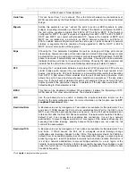
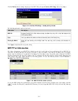
Page 141: ...that the user wishes to add to this MSTI ID Supported VIDs on the Switch range from ID number 1 to 4094 This parameter can only be utilized if the Type chosen is Add or Remove Click Apply to implement...

Page 142: ...current MSTP Port Information and can be used to update the port configuration for an MSTI ID If a loop occurs the MSTP function will use the port priority to select an interface to put into the forw...

Page 143: ...nce The default setting is 0 auto There are two options 0 auto Selecting this parameter for the internalCost will set quickest route automatically and optimally for an interface The default value is d...

Page 144: ...automatically block the port and send an alert to the administrator The Loopback Detection port will restart change to discarding state when the Loopback Detection Recover Time times out The Loopback...

Page 145: ...P standard specifies the necessary protocol and management elements to 1 Facilitate multi vendor inter operability and the use of standard management tools to discover and make available physical topo...

Page 146: ...parameter indicates the interval at which LLDP frames are transmitted on behalf of this LLDP agent The default value is 30 seconds Message TX Hold Multiplier 2 10 This parameter is a multiplier that d...

Page 147: ...Switch Basic LLDP Port Settings The following window is used to set up LLDP on individual port s on the Switch To view this window click L2 Features LLDP Basic LLDP Port Settings Figure 7 48 Basic LL...

Page 148: ...information information timeout and information insert remove Admin Status Use the drop down menu to choose TX_Only RX_Only TX_and_RX or Disabled Port Description Use the drop down menu to toggle Por...

Page 149: ...DES 3028 DES 3028P DES 3028G DES 3052 DES 3052P Layer 2 Fast Ethernet Managed Switch Figure 7 49 802 1 Extension LLDP Port Settings Table window 135...

Page 150: ...e the drop down menu to toggle among VLAN ID VLAN Name and All Use the drop down menu to toggle between Enabled and Disabled Protocol Identity Use the drop down menu to toggle among EAPOL LACP GVRP ST...

Page 151: ...e 7 50 802 3 Extension LLDP Port Settings Table window The following parameters can be set or displayed Parameter Description From To Select a port or group of ports using the pull down menus MAC PHY...

Page 152: ...Size Use the drop down menu to toggle Maximum Frame Size between Enabled and Disabled Click Apply to implement changes made LLDP Management Address Settings The following window is used to set up LLD...

Page 153: ...splays the IPV4 Address type Address Enter the LLDP management address in this field Port State Use the drop down menu to toggle the Port State between Enabled and Disabled Click Apply to implement ch...

Page 154: ...w this window click L2 Features LLDP LLDP Management Address Table Figure 7 53 LLDP Management Address Table window Use the drop down menu to select the type of Management Address enter an IP address...

Page 155: ...ES 3028G DES 3052 DES 3052P Layer 2 Fast Ethernet Managed Switch Figure 7 54 LLDP Local Port Brief Table window Click the View button to display additional information about entries on the LLDP Local...

Page 156: ...mote Port Table The following window is used to display the LLDP Remote Port Brief Table To view this window click L2 Features LLDP LLDP Remote Port Table Figure 7 55 LLDP Remote Port Brief Table wind...

Page 157: ...smissions warrant special consideration The Switch allows you to further tailor how priority tagged data packets are handled on your network Using queues to manage priority tagged data allows you to s...

Page 158: ...ded This results in the end user receiving all packets sent as quickly as possible thus prioritizing the queue and allowing for an uninterrupted stream of packets which optimizes the use of bandwidth...

Page 159: ...B6 C6 A7 B7 A8 A1 B1 C1 D1 E1 F1 G1 H1 For weighted round robin queuing if each CoS queue has the same weight value then each CoS queue has an equal opportunity to send packets just like round robin q...

Page 160: ...itch Port Bandwidth The bandwidth control settings are used to place a ceiling on the transmitting and receiving data rates for any selected port To view this window click CoS Port Bandwidth Figure 8...

Page 161: ...s No Limit This drop down menu allows you to specify that the selected port will have no bandwidth limit Enabled disables the limit Rate This field allows you to enter the data rate in Kbit s that wil...

Page 162: ...ssign a default 802 1p priority to any given port on the Switch The priority tags are numbered from 0 the lowest priority to 7 the highest priority To implement a new default priority choose a port ra...

Page 163: ...8 4 802 1p User Priority window Once you have assigned a priority to the port groups on the Switch you can then assign this Class to each of the four levels of 802 1p priorities Click Apply to set you...

Page 164: ...t Scheduling CoS can be customized by changing the output scheduling used for the hardware classes of service in the Switch As with any changes to CoS implementation careful consideration should be gi...

Page 165: ...ured here For example if a port has been assigned a MAC priority the packet that has the CoS priority assigned to a MAC address will be sent to the CoS queue configured for that MAC address Once the c...

Page 166: ...DES 3028 DES 3028P DES 3028G DES 3052 DES 3052P Layer 2 Fast Ethernet Managed Switch Figure 8 7 Priority Settings window 152...

Page 167: ...this option will assign ports to map CoS priorities to MAC addresses TOS Choosing this option will assign ports to map CoS priorities to ToS priorities DSCP Choosing this option will assign ports to...

Page 168: ...y of the available queues When a packet is received containing this DSCP tag it will be mapped to the CoS queue configured here These settings will only take effect if at least one of the priority set...

Page 169: ...a the given ingress port The frames will be assigned to either the highest queue or the lowest queue Please note the following limitation exists port based CoS only supports mapping to Queue 3 Port ma...

Page 170: ...igure the appropriate queue to be mapped to this destination MAC address using the following window 3 Once the previous parameters are set users should go to the Priority Settings window located in th...

Page 171: ...Press the Apply button to make the time range current Access Profile Table Access profiles allow you to establish criteria to determine whether or not the Switch will forward packets based on the info...

Page 172: ...umber for this profile set The number is used to set the relative priority for the profile Priority is set relative to other profiles where the lowest profile ID has the highest priority If a conflict...

Page 173: ...ong configured access rules the profile ID establishes relative priority of the rules The value can be set from 1 to 256 however there is a limit to the total number of profiles that can be created Ty...

Page 174: ...y also identify which flag bits to deny Flag bits are parts of a packet that determine what to do with the packet The user may deny packets by denying certain flag bits within the packets by checking...

Page 175: ...ket header Select IP to instruct the Switch to examine the IP address in each frame s header Select Packet Content Mask to specify a mask to hide the content of the packet header Offset This field wil...

Page 176: ...t ACL to prevent ARP spoofing attack please see Appendix E at the end of this manual To establish the rule for a previously created Access Profile To edit or add a rule to a previously created profile...

Page 177: ...d previously by the user When replace priority is selected the Switch will rewrite the 802 1p default priority of a packet to the value entered into the priority field This value will meet the criteri...

Page 178: ...If no entry exists only the Add button will be displayed however when an entry already exists a corresponding Modify button will also be displayed This will open the following window Figure 9 9 Access...

Page 179: ...g created Type Selected profile based on Ethernet MAC Address IP address or Packet Content Mask Ethernet instructs the Switch to examine the layer 2 part of each packet header IP instructs the Switch...

Page 180: ...et Type Specifies that the access profile will apply only to packets with this hexadecimal 802 1Q Ethernet type value hex 0x0 0xffff in the packet header The Ethernet type value may be set in the form...

Page 181: ...r the Access ID and click Find To display all rules in the table click the View All Entries button To add a new Access Rule click the Add button above the Access Rule Table window to view the Access R...

Page 182: ...are forwarded to the CoS queue specified previously by the user When replace priority is selected the Switch will rewrite the 802 1p default priority of a packet to the value entered into the priorit...

Page 183: ...hat to do with the frame The entire process is described below CPU Interface Filtering State In the following window the user may globally enable or disable the CPU Interface Filtering mechanism by us...

Page 184: ...r Select IP to instruct the Switch to examine the IP address in each frame s header Select Packet Content Mask to specify a mask to hide the content of the packet header VLAN Selecting this option ins...

Page 185: ...lect IP to instruct the Switch to examine the IP address in each frame s header Select Packet Content Mask to specify a mask to hide the content of the packet header VLAN Selecting this option instruc...

Page 186: ...ine what to do with the packet The user may filter packets by filtering certain flag bits within the packets by checking the boxes corresponding to the flag bits of the TCP field The user may choose b...

Page 187: ...the window according to the requirements for the type of profile Select Ethernet to instruct the Switch to examine the layer 2 part of each packet header Select IP to instruct the Switch to examine th...

Page 188: ...ly created CPU access profile by clicking the corresponding Modify button of the entry to configure Ethernet IP or Packet Content Mask Figure 9 21 CPU Interface Filtering Rule Table window Click the A...

Page 189: ...based on Ethernet MAC Address IP address or Packet Content Ethernet instructs the Switch to examine the layer 2 part of each packet header IP instructs the Switch to examine the IP address in each fr...

Page 190: ...ss rule will be implemented on the Switch To view the settings of a previously configured rule click in the Access Rule Table to view the following window Figure 9 23 CPU Interface Filtering Entry Dis...

Page 191: ...examine the layer 2 part of each packet header IP instructs the Switch to examine the IP address in each frame s header Packet Content Mask instructs the Switch to examine the packet header VLAN Name...

Page 192: ...le Table to view the following window window IP The following window is the CPU Interface Filtering Rule Table for Packet Content Figure 9 26 CPU Interface Filtering Entry Display To remove a previous...

Page 193: ...specify that packets that do not match the access profile are not forwarded by the Switch and will be filtered Access ID Type in a unique identifier number for this access This value can be set from...

Page 194: ...n hex form to mask the packet from byte 64 to byte 79 Port The CPU Access Rule may be configured on a per port basis by entering the port number of the Switch Time Range Click the check box and enter...

Page 195: ...and control the situation The packet storm is monitored to determine if too many packets are flooding the network based on the threshold level provided by the user Once a packet storm has been detecte...

Page 196: ...indow in the Administration folder and selecting the disabled port and returning it to an Enabled status alternatively the user can wait for the auto recovery function which will occur after 5 minutes...

Page 197: ...value stated and drop packets until the issue is resolved Shut Down Utilizes the Switch s software Traffic Control mechanism to determine the Packet Storm occurring Once detected the port will deny al...

Page 198: ...e seen as Discarding in Spanning Tree windows and implementations though these ports will still be forwarding BPDUs to the Switch s CPU NOTE Ports that are in rest mode will be seen as link down in al...

Page 199: ...Port Security window The following parameters can be set Parameter Description From To A consecutive group of ports may be configured starting with the selected port Admin State This pull down menu a...

Page 200: ...he Delete heading of the corresponding MAC address to be deleted Only entries marked Secured_Permanent can be deleted Click the Next button to view the next page of entries listed in this table This w...

Page 201: ...obal Settings This window is used to enable or disable the Trap Log State and DHCP Snoop state on the switch The Trap Log field will enable and disable the sending of trap log messages for IP MAC bind...

Page 202: ...er Description From Port To Port Select a port or range of ports to set for IP MAC Binding State Use the pull down menu to enable or disable these ports for IP MAC Binding Strict This mode provides a...

Page 203: ...P Packet By default the DHCP packet with broadcast DA will be flooded When set to disable the broadcast DHCP packet received by the specified port will not be forwarded Max Entry Specifies the maximum...

Page 204: ...ntries Figure 10 7 DHCP Snooping Entries window MAC Block List This table is used to view unauthorized devices that have been blocked by IP MAC binding restrictions To find an unauthorized device that...

Page 205: ...Switch to create a three layered encryption code for secure communication between the server and the host The user may implement any one or combination of the ciphersuites available yet different ciph...

Page 206: ...a der extension Ex c cert der Key File Name Enter the path and the filename of the key file to download This file must have a der extension Ex c pkey der To set up the SSL function on the Switch conf...

Page 207: ...Diffie Hellman key exchange CBC Block Cipher 3DES_EDE encryption and SHA Hash Algorithm Use the pull down menu to enable or disable this ciphersuite This field is Enabled by default RSA EXPORT with RC...

Page 208: ...ount on the Switch including specifying a password This password is used to logon to the Switch once a secure communication path has been established using the SSH protocol 2 Configure the User Accoun...

Page 209: ...ed the Switch will be disconnected and the user must reconnect to the Switch to attempt another login The number of maximum attempts may be set between 2 and 20 The default setting is 2 Session Rekeyi...

Page 210: ...S192 encryption algorithm with Cipher Block Chaining The default is Enabled AES256 CBC Use the pull down to enable or disable the Advanced Encryption Standard AES 256 encryption algorithm with Cipher...

Page 211: ...parameter should be chosen to use a remote SSH server for authentication purposes Choosing this parameter requires the user to input the following information to identify the SSH user Host Name Enter...

Page 212: ...e authenticated client via SNMP on R2 with the Radius command item in auth mib OID 1 3 6 1 4 1 171 12 3 7 by port based or Host based NOTE If the session timeout attribute on the radius server is set...

Page 213: ...es services Figure 10 16 The Authentication Server Authenticator The Authenticator the Switch is an intermediary between the Authentication Server and the Client The Authenticator servers two purposes...

Page 214: ...is granted access and therefore successfully unlocks the port Once unlocked normal traffic is allowed to pass through the port The following figure displays a more detailed explanation of how the auth...

Page 215: ...802 1X Client 802 1X Client 802 1X Client 802 1X Client 802 1X Client Network access controlled port Network access uncontrolled port Figure 10 20 Example of Typical Port Based Configuration Once the...

Page 216: ...number of distinct logical Ports each logical Port being independently controlled from the point of view of EAPOL exchanges and authorization state The Switch learns each attached devices individual...

Page 217: ...attribute but authenticates successfully the device will not assign a priority to this port If the priority attribute configured on the RADIUS is a value out of range 7 it will not be set to the devi...

Page 218: ...st based cannot undergo this procedure 2 Ports supporting Guest VLANs cannot be GVRP enabled and vice versa 3 A port cannot be a member of a Guest VLAN and a static VLAN simultaneously 4 Once a client...

Page 219: ...enticator Settings To configure the 802 1X Authenticator Settings click Security 802 1X 802 1X Authenticator Settings Figure 10 23 802 1X Authenticator Settings window To configure the settings by por...

Page 220: ...ent If forceUnauthorized is selected the port will remain in the unauthorized state ignoring all attempts by the client to authenticate The Switch cannot provide authentication services to the client...

Page 221: ...thentication server The default setting is 30 seconds MaxReq The maximum number of times that the Switch will retransmit an EAP Request to the client before it times out of the authentication sessions...

Page 222: ...al users on the Switch To view this window click Security 802 1X 802 1X User Figure 10 25 Local Users Configuration window Enter a User Name Password and confirmation of that password Properly configu...

Page 223: ...on the Switch To view this window click Security 802 1X 802 1X Capability Settings Figure 10 26 802 1X Capability Settings window Configure 802 1X Guest VLAN In order to configure a Guest 802 1X VLAN...

Page 224: ...s listed in the Port List below as part of the Guest VLAN Be sure that these ports are configured for this VLAN or users will be prompted with an error message Port List Set the port list of ports to...

Page 225: ...indicating a port on the Switch Initializing Ports for Host Based 802 1X To initialize ports for the Host side of 802 1X the user must first enable 802 1X by MAC address in the DES 30xx Web Managemen...

Page 226: ...le window This window displays the following information Parameter Description Port The port number of the reauthenticated port Auth State The Authenticator State will display one of the following Ini...

Page 227: ...orts first choose the range of ports in the From and To field Then the user must specify the MAC address to be reauthenticated by entering it into the MAC Address field and checking the corresponding...

Page 228: ...ared key is the same as that of the RADIUS server Status This allows users to set the RADIUS Server as Valid Enabled or Invalid Disabled Trusted Host To view the Trusted Host settings on the switch cl...

Page 229: ...rname and password and the user is granted normal user privileges on the Switch The server will not accept the username and password and the user is denied access to the Switch The server doesn t resp...

Page 230: ...0 and 255 seconds The default setting is 30 seconds User Attempts 1 255 This command will configure the maximum number of times the Switch will accept authentication attempts Users failing to be auth...

Page 231: ...use the default Method List or other Method List configured by the user See the Enable Method Lists window in this section for more information Click Apply to implement changes made Authentication Ser...

Page 232: ...sts to the list Authentication Server Hosts must be configured for their specific protocol on a remote centralized server before this function can work properly NOTE The four built in server groups ca...

Page 233: ...ost click the IP address hyperlink revealing the following window Figure 10 41 Authentication Server Host Setting Edit window Configure the following parameters to add an Authentication Server Host Pa...

Page 234: ...or higher security Timeout 1 255 Enter the time in seconds the Switch will wait for the server host to reply to an authentication request The default value is 5 seconds Retransmit 1 255 Enter the valu...

Page 235: ...user When the local method is used the privilege level will be dependant on the local account privilege configured on the Switch Successful login using any of these techniques will give the user a Us...

Page 236: ...cess the Switch Enable Method Lists The Enable Method List Settings window is used to set up Method Lists to promote users with user level privileges to Administrator Admin level privileges using auth...

Page 237: ...d To modify an Enable Method List click on its hyperlinked Method List Name To configure a Method List click the Add button Both actions will result in the same window to configure Figure 10 46 Enable...

Page 238: ...will require the user to be authenticated using the RADIUS protocol from a remote RADIUS server tacacs Adding this parameter will require the user to be authenticated using the TACACS protocol from a...

Page 239: ...the New Local Enabled field will result in a fail message Enable Admin Figure 10 49 Enable Admin window The Enable Admin window is for users who have logged on to the Switch on the normal user level...

Page 240: ...h This method of segmenting the flow of traffic is similar to using VLANs to limit traffic but is more restrictive It provides a method of directing traffic that does not increase the overhead of the...

Page 241: ...inst a network This attack is designed to stop a network from functioning by flooding it with useless traffic Symptoms of a malicious attack include the inability to access any web site or a particula...

Page 242: ...ith the source host port the same as the destination host port the system then attempts to reply to itself which causes the system to lock up Smurf Attack A Smurf attack works by sending PING requests...

Page 243: ...default services then uses the L4 port between 1 and 1023 All Check this box to select all attack types Action Set Action to Drop or Mirror the selected types of attacks State Set the State to Enabled...

Page 244: ...ES 3052P Layer 2 Fast Ethernet Managed Switch Figure 10 56 DoS Smurf Attack Prevention window Summary window Figure 10 57 DoS TCP Null Scan Prevention window Summary window Figure 10 58 DoS TCP Xmasca...

Page 245: ...3028P DES 3028G DES 3052 DES 3052P Layer 2 Fast Ethernet Managed Switch Figure 10 59 DoS TCP SYNFIN Prevention window Summary window Figure 10 60 DoS TCP SYN SrcPort less 1024 Prevention window Summar...

Page 246: ...oup Browse Router Port VLAN Status MLD Snooping Group Browse MLD Snooping Router Port Static ARP Settings ARP FDB Gratuitous ARP Settings Session Table Port Access Control CPU Utilization The CPU Util...

Page 247: ...60s where s stands for seconds The default value is one second Record Number Select number of times the Switch will be polled between 20 and 200 The default value is 200 Show Hide Check whether to dis...

Page 248: ...ield can be set Parameter Description Time Interval Select the desired setting between 1s and 60s where s stands for seconds The default value is one second Record Number Select number of times the Sw...

Page 249: ...statistics for use the Port pull down menu The user may also use the real time graphic of the Switch at the top of the web page by simply clicking on a port To view this window click Monitoring Packe...

Page 250: ...ort Packets Counts the number of packets received on the port Unicast Counts the total number of good packets that were received by a unicast address Multicast Counts the total number of good packets...

Page 251: ...atistics for use the Port pull down menu The user may also use the real time graphic of the Switch at the top of the web page by simply clicking on a port To view this window click Monitoring Packets...

Page 252: ...ult value is 200 Unicast Counts the total number of good packets that were received by a unicast address Multicast Counts the total number of good packets that were received by a multicast address Bro...

Page 253: ...these statistics for use the Port pull down menu The user may also use the real time graphic of the Switch at the top of the web page by simply clicking on a port To view this window click Monitoring...

Page 254: ...om the port Packets Counts the number of packets successfully sent on the port Unicast Counts the total number of good packets that were transmitted by a unicast address Multicast Counts the total num...

Page 255: ...g graph displays error packets received by the Switch To select a port to view these statistics for select the port by using the Port pull down menu The user may also use the real time graphic of the...

Page 256: ...rrence OverSize Counts packets received that were longer than 1518 octets or if a VLAN frame is 1522 octets and less than the MAX_PKT_LEN Internally MAX_PKT_LEN is equal to 1522 Fragment The number of...

Page 257: ...tistics for select the port by using the Port pull down menu The user may also use the real time graphic of the Switch at the top of the web page by simply clicking on a port To view this window click...

Page 258: ...octet boundary LateColl Counts the number of times that a collision is detected later than 512 bit times into the transmission of a packet ExColl Excessive Collisions The number of packets for which t...

Page 259: ...le Two windows are offered To select a port to view these statistics for select the port by using the Port pull down menu The user may also use the real time graphic of the Switch at the top of the we...

Page 260: ...ere between 128 and 255 octets in length inclusive excluding framing bits but including FCS octets 256 511 The total number of packets including bad packets received that were between 256 and 511 octe...

Page 261: ...address forwarding table to be viewed When the Switch learns an association between a MAC address and a port number it makes an entry into its forwarding table These entries are then used to forward...

Page 262: ...port VLAN or MAC address VID The VLAN ID of the VLAN of which the MAC address above corresponds MAC Address The MAC address entered into the address table Port The port to which the MAC address corre...

Page 263: ...ap receiving stations and to the PC connected to the console manager Click Next to go to the next page of the Switch History Log Clicking Clear will allow the user to clear the Switch History Log The...

Page 264: ...ring it in the top left hand corner and clicking Search The user may also delete Data Driven learning entries by entering the VLAN Name and clicking Delete or Delete All Data Driven learning Entries T...

Page 265: ...the Switch s ports to be viewed by VLAN This window displays the ports on the Switch that are currently Egress E or Tag T ports This window displays the ports on the Switch that are currently Egress E...

Page 266: ...E To configure MLD snooping for the Switch go to the L2 Features folder and select MLD Snooping MLD Snooping Settings Browse MLD Snooping Router Port This window displays which of the Switch s ports a...

Page 267: ...ow To modify an entry select it on the ARP Settings table and click Modify Figure 11 24 Static ARP Settings Edit window ARP FDB This window conveniently allows the user to add entries to the IP MAC Po...

Page 268: ...tch Figure 11 25 ARP FDB window To search for information regarding a specific entry enter the appropriate information and click Find The ARP FDB entries will be displayed in the ARP FDB Table to add...

Page 269: ...ption Send on IPIF status up This is used to enable disable the sending of gratuitous ARP request packets while an IPIF interface comes up This is used to automatically announce the interface s IP add...

Page 270: ...There are six windows to monitor NOTE The Authenticator State Authenticator Statistics Authenticator Session Statistics and Authenticator Diagnostics windows in this section cannot be viewed on the Sw...

Page 271: ...redths of a second between the most recent Access Reply Access Challenge and the Access Request that matched it from this RADIUS authentication server AccessRetrans The number of RADIUS Access Request...

Page 272: ...etry to the same server is counted as a retransmit as well as a timeout A send to a different server is counted as an Accounting Request as well as a timeout Requests The number of RADIUS Accounting R...

Page 273: ...on has several options when resetting the Switch Some of the current configuration parameters can be retained while resetting all other configuration parameters to their factory defaults NOTE Only the...

Page 274: ...ick the Restart button to restart the Switch Save Changes The Switch has two levels of memory normal RAM and non volatile or NV RAM Configuration changes are made effective clicking the Apply button W...

Page 275: ...DES 3028 DES 3028P DES 3028G DES 3052 DES 3052P Layer 2 Fast Ethernet Managed Switch Logout Click the Logout button on the Logout window to immediately exit the Switch Figure 11 34 Logout window 261...

Page 276: ...0BASE FX DEM 211 Multi Mode 100BASE FX WDM Transceivers Supported DEM 330T TX 1550 RX 1310nm up to 10km Single Mode DEM 330R TX 1310 RX 1550nm up to 10km Single Mode DEM 331T TX 1550 RX 1310nm up to 4...

Page 277: ...cm fan and one 17cm fan Operating Temperature 0 40 C Storage Temperature 40 70 C Humidity 5 95 non condensing Dimensions DES 3028 DES 3028G 441 W x 207 D x 44 H mm DES 3028P 3052 3052P 441 W x 309 D x...

Page 278: ...ts remain active 4 Active circuit protection automatically disables the port if there is a short while other ports remain active 5 PD should be able to receive the power following the classification b...

Page 279: ...inking Port has detected a error condition LED Per 10 100 Mbps Port PoE only for DES 3028P DES 3052P Green Light off Powered Device may receive power from an AC power source or no 802 3af PD is found...

Page 280: ...ons Feature Detailed Description Console Port DCE RS 232 DB 9 for out of band configuration of the software features 24 x 10 100BaseT ports 48 x 10 100BaseT ports Power over LAN support Compliant to f...

Page 281: ...DEM 331R TX 1310 RX 1550nm up to 40km Single Mode Compliant to following standards 1 IEEE 802 3z compliance 2 IEEE 802 3u compliance 1000BASE T ports in the front panel 1000BASE T ports compliant to...

Page 282: ...n and log saved to flash Username username IP ipaddr MAC macaddr Informational Configuration and log saved to flash by console Configuration and log saved to flash by console Username username Informa...

Page 283: ...essfully uploaded by console Log message successfully uploaded by console Username username Informational Log message upload was unsuccessful Log message upload was unsuccessful Username username IP i...

Page 284: ...rning Logout through Telnet Logout through Telnet Username username IP ipaddr Informational Telnet session timed out Telnet session timed out Username username IP ipaddr Informational SNMP SNMP reques...

Page 285: ...od Username username Warning Successful login through Web authenticated by AAA local method Successful login through Web from userIP authenticated by AAA local method Username username Informational L...

Page 286: ...h Telnet authenticated by AAA none method Successful login through Telnet from userIP authenticated by AAA none method Username username Informational Successful login through SSH authenticated by AAA...

Page 287: ...thenticated by AAA server Login failed through Telnet from userIP authenticated by AAA server serverIP Username username Warning Login failed through Telnet due to AAA server timeout or improper confi...

Page 288: ...t authenticated by AAA local_enable method Successful Enable Admin through Telnet from userIP authenticated by AAA local_enable method Username username Informational Enable Admin failed through Telne...

Page 289: ...erIP Username username Warning Enable Admin failed through Console due to AAA server timeout or improper configuration Enable Admin failed through Console due to AAA server timeout or improper configu...

Page 290: ...Admin through SSH from userIP authenticated by AAA server serverIP Username username Informational Enable Admin failed through SSH authenticated by AAA server Enable Admin failed through SSH from use...

Page 291: ...detected with this device Conflict IP was detected with this device IP ipaddr MAC macaddr Port portNum Interface interface Informational 802 1X Radius server assigned VID to port Radius server r serve...

Page 292: ...caddr Informational Loopback Detection Port Loop occurred Configuration Testing Protocol detects a loop in port portNum Informational Standard Trap List Trap Name OID Variable Bind Format MIB Name ris...

Page 293: ...dingViolationMac V2 IP MAC BIND MIB agentGratuitousARPTrap 1 3 6 1 4 1 171 12 1 7 2 0 5 agentGratuitousARPIpAddr agentGratuitousARPMacAddr agentGratuitousARPPortNumber agentGratuitousARPInterfaceNa me...

Page 294: ...DES 3028 DES 3028P DES 3028G DES 3052 DES 3052P Layer 2 Fast Ethernet Managed Switch 1 3 6 1 4 1 171 11 63 11 2 20 0 1 280...

Page 295: ...Standard Media Type Maximum Distance Mini GBIC 1000BASE LX Single mode fiber module 1000BASE SX Multi mode fiber module 1000BASE LHX Single mode fiber module 1000BASE ZX Single mode fiber module 10km...

Page 296: ...is a direct connection to the console port of the device It is necessary for the user needs to attach a terminal or PC with terminal emulation to the console port of the switch 2 Power on the switch...

Page 297: ...itch Command Parameters accounts reset password username The reset password command resets the password of the specified user If a username is not specified the password of all users will be reset sho...

Page 298: ...volved Bridges form a single logical network centralizing network administration broadcast A message sent to all destination devices on the network broadcast storm Multiple simultaneous broadcasts tha...

Page 299: ...protocol which allows IP to run over a serial line connection SNMP Simple Network Management Protocol A protocol originally designed to be used in managing TCP IP internets SNMP is presently implement...

Page 300: ...s IP address will be written into the Sender Protocol Address in ARP payload As PC B s MAC address is unknown the Target H W Address will be 00 00 00 00 00 00 while PC B s IP address will be written i...

Page 301: ...frame to all ports except the source port port 1 see Figure 2 Figure 2 When the switch floods the frame of the ARP request to the network all PCs will receive and examine the frame but only PC B will...

Page 302: ...query Destination Address in the Ethernet frame it will change to PC A s MAC address The Source Address will be changed to PC B s MAC address see Table 4 Destination address 00 20 5C 01 11 11 Source...

Page 303: ...be mistakenly re directed to the node specified by the attacker IP spoofing attacks are caused by Gratuitous ARPs that occur when a host sends an ARP request to resolve its own IP address Figure 4 sho...

Page 304: ...pecified MAC address to the IP address of the network s default gateway The malicious attacker only needs to broadcast ONE Gratuitous ARP to the network claiming it is the gateway so that the whole ne...

Page 305: ...o 80 bytes in total at one time It utilizes offsets to match individual fields in the Ethernet Frame An offset contains 16 bytes and the switch supports 5 offsets with each offset being divided into a...

Page 306: ......

Page 307: ......

Page 308: ...stic environment this product may cause radio interference in which case the user may be required to take adequate measures Warnung Dies ist ein Produkt der Klasse A Im Wohnbereich kann dieses Produkt...

Page 309: ...y WARNING When working with laser optic modules always take the following precautions to avoid exposure to hazardous radiation Never look at the transmit LED laser through a magnifying device while it...

Page 310: ...the original licensee and is subject to the terms and conditions of the license granted by D Link for the Software The Warranty Period shall extend for an additional ninety 90 days after any replaceme...

Page 311: ...K FOR WARRANTY SERVICE RESULTING FROM THE USE OF THE PRODUCT RELATING TO WARRANTY SERVICE OR ARISING OUT OF ANY BREACH OF THIS LIMITED WARRANTY EVEN IF D LINK HAS BEEN ADVISED OF THE POSSIBILITY OF SU...

Page 312: ...returned to D Link The license granted respecting any Software for which a refund is given automatically terminates Non Applicability of Warranty The Limited Warranty provided hereunder for Hardware a...

Page 313: ...or limitation of incidental or consequential damages or limitations on how long an implied warranty lasts so the foregoing limitations and exclusions may not apply This Limited Warranty provides speci...

Page 314: ...egistration Register your D Link product online at http support dlink com register Product registration is entirely voluntary and failure to complete or return this form will not diminish your warrant...

Page 315: ...all material respects to the defective Hardware The Warranty Period shall extend for an additional ninety 90 days after any repaired or replaced Hardware is delivered If a material defect is incapable...

Page 316: ...ted provide written proof of purchase of the product such as a copy of the dated purchase invoice for the product before the warranty service is provided After an RMA number is issued the defective pr...

Page 317: ...EGAL OR EQUITABLE THEORY FOR ANY LOSS OF USE OF THE PRODUCT INCONVENIENCE OR DAMAGES OF ANY CHARACTER WHETHER DIRECT SPECIAL INCIDENTAL OR CONSEQUENTIAL INCLUDING BUT NOT LIMITED TO DAMAGES FOR LOSS O...

Page 318: ...uipment has been tested and found to comply with the limits for a Class A digital device pursuant to Part 15 of the FCC Rules These limits are designed to provide reasonable protection against harmful...

Page 319: ...warranty period on this product U S and Canadian customers can contact D Link technical support through our website or by phone Tech Support for customers within the United States D Link Technical Su...

Page 320: ...uk ftp ftp dlink co uk Technische Unterst tzung Deutschland Web http www dlink de E Mail support dlink de Telefon 49 0 1805 2787 0 14 pro Minute Zeiten Mo Fr 09 00 17 30 Uhr sterreich Web http www dl...

Page 321: ...al venerd dalle ore 9 00 alle ore 19 00 con orario continuato 0 067 min De Lunes a Viernes de 9 00 a 14 00 y de 15 00 a 18 00 http www dlink es Asistencia T cnica Asistencia T cnica Telef nica de D L...

Page 322: ...e 14 99 HUG min Mobile 49 99 HUF min email support dlink hu URL http www dlink hu Web http www dlink cz suppport E mail support dlink cz Telefon 225 281 553 Telefonick podpora je v provozu PO P od 09...

Page 323: ...ink Teknisk Support via telefon 0900 100 77 00 Vardagar 08 00 20 00 D Link Teknisk Support via Internet http www dlink se Assist ncia T cnica Assist ncia T cnica da D Link na Internet http www dlink p...

Page 324: ...a podpora Zahvaljujemo se vam ker ste izbrali D Link proizvod Za vse nadaljnje informacije podporo ter navodila za uporabo prosimo obi ite D Link ovo spletno stran www dlink eu www dlink biz sl Suport...

Page 325: ...ys http www dlink co in support productsupport aspx Indonesia Malaysia Singapore and Thailand Tel 62 21 5731610 Indonesia Tel 1800 882 880 Malaysia Tel 65 66229355 Singapore Tel 66 2 719 8978 9 Thaila...

Page 326: ...92 21 4548158 or 92 21 4548310 Monday to Friday 10 00am to 6 00pm http support dlink me com E mail zkashif dlink me com South Africa and Sub Sahara Region Tel 27 12 665 2165 08600 DLINK for South Afri...

Page 327: ...D Link D Link D Link D Link 7 495 744 00 99 http www dlink ru e mail support dlink ru...

Page 328: ...06 00am a 19 00pm Costa Rica 0800 0521478 Lunes a Viernes 05 00am a 18 00pm Ecuador 1800 035465 Lunes a Viernes 06 00am a 19 00pm El Salvador 800 6335 Lunes a Viernes 05 00am a 18 00pm Guatemala 1800...

Page 329: ...l A D Link fornece suporte t cnico gratuito para clientes no Brasil durante o per odo de vig ncia da garantia deste produto Suporte T cnico para clientes no Brasil Telefone S o Paulo 11 2185 9301 Segu...

Page 330: ...D Link D Link D Link 0800 002 615 9 00 9 00 http www dlink com tw dssqa_service dlink com tw D Link http www dlink com tw...

Page 331: ...kumentasi pengguna dapat diperoleh pada situs web D Link Dukungan Teknis untuk pelanggan Dukungan Teknis D Link melalui telepon Tel 62 21 5731610 Dukungan Teknis D Link melalui Internet Email support...

Page 332: ...Technical Support Web Web URL http www dlink jp com...

Page 333: ...D Link 36 B 26F 02 05 100013 8008296688 028 66052968 028 85176948 36 B 26F 02 05 100013 010 58257789 010 58257790 http www dlink com cn 09 00 18 00...

Reviews: