background image

D-Link DES-3250TG Standalone Layer 2 Switch


NOTICE:

 A NOTICE indicates either potential damage to hardware or loss 

of data and tells you how to avoid the problem. 


CAUTION:

 A CAUTION indicates a potential for property damage, 

personal injury, or death. 


Safety Instructions 

Use the following safety guidelines to ensure your own personal safety and to help protect your system from potential damage. 
Throughout this safety section, the caution icon  (     ) is used to indicate cautions and precautions that you need to review and 
follow. 


Safety Cautions 


To reduce the risk of bodily injury, electrical shock, fire, and damage to the equipment, observe the following precautions. 
 
Observe and follow service markings. Do not service any product except as explained in your system documentation. Opening 
or removing covers that are marked with the triangular symbol with a lightning bolt may expose you to electrical shock. Only 
a trained service technician should service components inside these compartments. 
If any of the following conditions occur, unplug the product from the electrical outlet and replace the part or contact your 
trained service provider: 

– The power cable, extension cable, or plug is damaged. 
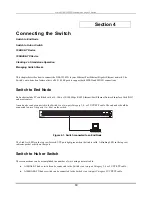
– An object has fallen into the product. 
– The product has been exposed to water. 
– The product has been dropped or damaged. 
– The product does not operate correctly when you follow the operating instructions. 

• 

Keep your system away from radiators and heat sources. Also, do not block cooling vents. 

• 

Do not spill food or liquids on your system components, and never operate the product in a wet environment. If the 
system gets wet, see the appropriate section in your troubleshooting guide or contact your trained service provider. 

• 

Do not push any objects into the openings of your system. Doing so can cause fire or electric shock by shorting out 
interior components. 

• 

Use the product only with approved equipment. 

• 

Allow the product to cool before removing covers or touching internal components. 

• 

Operate the product only from the type of external power source indicated on the electrical ratings label. If you are 
not sure of the type of power source required, consult your service provider or local power company. 

• 

To help avoid damaging your system, be sure the voltage selection switch (if provided) on the power supply is set to 
match the power available at your location: 

– 115 volts (V)/60 hertz (Hz) in most of North and South America and some Far Eastern countries such as South 
Korea and Taiwan 
– 100 V/50 Hz in eastern Japan and 100 V/60 Hz in western Japan 
– 230 V/50 Hz in most of Europe, the Middle East, and the Far East 

• 

Also be sure that attached devices are electrically rated to operate with the power available in your location. 

• 

Use only approved power cable(s). If you have not been provided with a power cable for your system or for any AC-
powered option intended for your system, purchase a power cable that is approved for use in your country. The power 
cable must be rated for the product and for the voltage and current marked on the product's electrical ratings label. 
The voltage and current rating of the cable should be greater than the ratings marked on the product. 

viii


Summary of Contents for DES-3250TG

Page 1: ...D Link DES 3250TG Stackable Layer 2 Switch User s Guide ____________________...

Page 2: ...ly forbidden Trademarks used in this text D Link and the D Link logo are trademarks of D Link Computer Corporation Microsoft and Windows are registered trademarks of Microsoft Corporation Other tradem...

Page 3: ...anel 7 Rear Panel 7 Side Panels 8 Gigabit Combo Ports 8 LED Indicators 8 Connecting the Switch 10 Switch to End Node 10 Switch to Hub or Switch 10 10BASE T Device 11 100BASE TX Device 11 Stacking vs S...

Page 4: ...IGMP Snooping 43 Static Router Ports Entry 45 Spanning Tree 46 STP Switch Settings 48 STP Port Settings 50 Forwarding Filtering 53 Unicast Forwarding 53 Multicast Forwarding 53 VLANs 55 Static VLAN En...

Page 5: ...112 SNMPV3 113 SNMP User Table 113 SNMP View Table 115 SNMP Group Table 117 SNMP Community Table 119 SNMP Host Table 120 SNMP Engine ID 121 Monitoring 122 CPU Utilization 122 Port Utilization 123 Pack...

Page 6: ...Layer 2 Switch Reset 149 Reset System 149 Reset Config 150 Logout 150 Appendix A 150 Technical Specifications 150 Appendix B 153 Understanding and Troubleshooting the Spanning Tree Protocol 153 Warra...

Page 7: ...cting devices to the Switch Section 7 Configuration A detailed discussion about configuring some of the basic functions of the Switch including accessing the Switch information using the Switch s util...

Page 8: ...o not spill food or liquids on your system components and never operate the product in a wet environment If the system gets wet see the appropriate section in your troubleshooting guide or contact you...

Page 9: ...to the power supply Unplug the power cable before removing the power supply If the system has multiple sources of power disconnect power from the system by unplugging all power cables from the power...

Page 10: ...y or an electrician if you are uncertain that suitable grounding is available CAUTION The system chassis must be positively grounded to the rack cabinet frame Do not attempt to connect power to the sy...

Page 11: ...ilizing the same packet structure format and support for full duplex and management objects but with a tenfold increase in theoretical throughput over 100Mbps Fast Ethernet and a one hundred fold incr...

Page 12: ...er port at 100 of wire speed for 100Mbps speed Data filtering rate eliminates all error packets runts etc at 14 880 pps per port at 100 of wire speed for 10Mbps speed Data filtering rate eliminates al...

Page 13: ...Fast Spanning Tree Algorithm Protocol for creation of alternative backup paths and prevention of network loops SNMP V1 V2C and V3 are supported Fully configurable in band control for SNMP based softwa...

Page 14: ...al D Link reseller for replacement Installation Use the following guidelines when choosing a place to install the Switch The surface must support at least 5 kg The power outlet should be within 1 82 m...

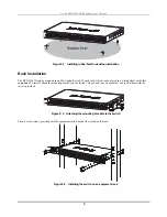
Page 15: ...ck which can be placed in a wiring closet with other equipment To install attach the mounting brackets on the switch s side panels one on each side and secure them with the screws provided Figure 2 2...

Page 16: ...r the power switch is turned on the LED indicators should respond as follows All LED indicators will momentarily blink This blinking of the LED indicators represents a reset of the system The power LE...

Page 17: ...sole port for setting up and managing the switch via a connection to a console terminal or PC using a terminal emulation program Forty eight high performance NWay Ethernet ports all of which operate a...

Page 18: ...ventilation Be reminded that without proper heat dissipation and air circulation system components might overheat which could lead to system failure Gigabit Combo Ports In addition to the 48 10 100 Mb...

Page 19: ...ready state of the device Console This indicator is lit green when the switch is being managed via local console management through the RS 232 console port Link Act These indicators are located to th...

Page 20: ...t Ethernet Network Interface Card NIC and most routers An end node can be connected to the Switch via a two pair Category 3 4 or 5 UTP STP cable The end node should be connected to any of the ports 1x...

Page 21: ...tart and the negotiation process begins anew When the stacking mode is disabled config stacking mode disable the Switch only allows standalone operation If stacking mode is disabled on a Switch it sho...

Page 22: ...a standalone device even if a stacking module is installed To force standalone operation it is necessary to use the CLI command config stacking mode disable A Switch that has stacking mode disabled s...

Page 23: ...tches are added to or taken out of a stacked group of DES 3250TG Switches it is necessary to change the composition of a Switch stack and rearrange the stacking connections If a stacking link fails or...

Page 24: ...onvenient where multiple Switch stacks are installed so it is always clear which unit should be used to uplink Figure 4 3 Convert a Standalone Switch to a Stacked Switch Both Switches are now powered...

Page 25: ...his case we can preserve all the same configuration settings by downloading the previously saved configuration files to the replacement Switch Before disconnecting the network connections of the origi...

Page 26: ...When stacked in a star topology arrangement with the DGS 3312SR the Switch will automatically assume slave status The unit number is determined by the port number to which it is connected on the DGS 3...

Page 27: ...ace After you have successfully installed the Switch you can configure the Switch monitor the LED panel and display statistics graphically using a web browser such as Netscape Navigator version 6 2 an...

Page 28: ...et up the terminal plug the power cable into the power receptacle on the back of the Switch The boot sequence appears in the terminal 10 After the boot sequence completes the console login screen disp...

Page 29: ...the Switch or changing its settings This section tells how to log onto the Switch NOTE The passwords used to access the Switch are case sensitive therefore S is not the same as s When you first conne...

Page 30: ...he command prompt DES 3250TG 4 shown below Figure 5 3 Command Prompt NOTE The first user automatically gets Administrator level privileges It is recommended to create at least one Admin level user acc...

Page 31: ...er Figure 5 4 Creation of a new Admin level account NOTICE CLI configuration commands only modify the running configuration file and are not saved when the Switch is rebooted To save all your configur...

Page 32: ...be allowed to perform or be restricted from performing specific SNMP management functions The functions allowed or restricted are defined using the Object Identifier OID associated with a specific MIB...

Page 33: ...s represent the IP address to be assigned to the IP interface named System and the y s represent the corresponding subnet mask Alternatively you can enter config ipif System ipaddress xxx xxx xxx xxx...

Page 34: ...an SFP transceiver port Use your cabling requirements to select an appropriate SFP transceiver type Insert the SFP transceiver sold separately into the SFP transceiver slot Use the appropriate network...

Page 35: ...console program Note This Web based Management Module does not accept Chinese language input or other languages requiring 2 bytes per character Login to Web Manager The first step in getting started i...

Page 36: ...effective 3 A listing of all user accounts and access levels is shown in the User Account Management window This list is updated when Apply is executed Click Show All User Account Entries to access t...

Page 37: ...y normal RAM and non volatile or NV RAM Configuration changes are made effective by clicking the Apply button When this is done the settings will be immediately applied to the switching software in RA...

Page 38: ...hows the user interface The user interface is divided into 3 distinct areas as described in the table Area 1 Area 2 Area 3 Figure 6 6 Main Web Manager window Area Function 1 Presents a graphical near...

Page 39: ...width SNTP Settings Port Security QoS MAC Notification LACP Access Profile Table System Log Servers PAE Access Entity and Layer 3 IP Networking Management Contains windows concerning configurations fo...

Page 40: ...rt Configuration Port Mirroring Stack Setting Static ARP Settings IGMP Spanning Tree Forwarding Filtering VLANs Port Bandwidth SNTP Settings Port Security QoS LACP Access Profile Table System Log Host...

Page 41: ...ter the IP address of the gateway If you will manage the switch from the subnet on which it is installed you can leave the default address in this field If no VLANs have been previously configured on...

Page 42: ...0 and 255 This address should be a unique address on a network assigned to you by the central Internet authorities Subnet Mask A Bitmask that determines the extent of the subnet that the Switch is on...

Page 43: ...installed and the switch s MAC Address assigned by the factory and unchangeable In addition the Boot PROM Version and Firmware Version numbers are shown This information is helpful to keep track of P...

Page 44: ...ooping Disabled IGMP Snooping allows the switch to read the Multicast Group IP address and the corresponding MAC address from IGMP packets that pass through the switch It can be enabled globally by to...

Page 45: ...and Line Interface or for a Telnet session Figure 7 4 Serial Port Settings window The Serial Port Settings window is used to change and view the Console settings for your switch The default Baud Rate...

Page 46: ...he time between 1 and 2 147 483 647 seconds between MAC notifications The default setting is 1 second MAC Notification History Size The maximum number of entries listed in the history log used for not...

Page 47: ...allows the port to automatically determine the fastest settings the port on the device connected to the DES 3250TG can handle and then use those settings The 10_auto setting allows the port to automa...

Page 48: ...uto Toggle the Speed Duplex field to either select the speed and duplex half duplex state of the port Auto auto negotiation between 10 and 100 Mbps devices full or half duplex The Auto setting allows...

Page 49: ...and To pull down menu to choose a port or range of ports to describe and Unit to choose the Switch in the switch stack and then enter a description of the port s Click Apply to set the descriptions in...

Page 50: ...red to a slower port one of the 48 100 Mbps Fast Ethernet ports because many packets will be dropped The following fields can be set Parameter Description Source Port Allows multiple ports to be mirro...

Page 51: ...ch When the stacking mode is enabled the Switch may function in a properly connected and configured Switch stack By default the Switch has the stacking mode enabled When enabled the stacking mode can...

Page 52: ...witch Note that the stacking port is included in the total count Mode The field displays the method used to determine the stacking order of the Switches in the Switch stack Version The field displays...

Page 53: ...dow will appear Figure 7 11 Static ARP Settings Add window The following fields can be set or viewed Parameter Description IP Address The IP address of the ARP entry MAC Address The MAC address of the...

Page 54: ...specifies the length of time between sending IGMP queries Max Response Time Sets the maximum amount of time allowed before sending an IGMP response report A value between 1 and 25 seconds can be ente...

Page 55: ...GMP query packets Non Querier will denote that the router is not sending out IGMP query packets This field will only read Querier when the Querier State and the State fields have been Enabled State Th...

Page 56: ...on VID Displays the name of the VLAN ID the static router port belongs to VLAN Name Displays the name of the VLAN the static router port belongs to Member Ports Each port can be set individually as a...

Page 57: ...ansition states disabled blocking or listening or in the RSTP port state discarding there is no functional difference the port is not active in the network topology Table 5 1 below compares how the tw...

Page 58: ...ection of RSTP The protocol also provides for a variable used for migration in the event that legacy equipment on a segment is updated to use RSTP STP Switch Settings In the Configuration folder open...

Page 59: ...4 to 30 seconds This is the time any port on the switch spends in the listening state while moving from the blocking state to the forwarding state Bridge Priority 0 65535 Sec 32768 A Bridge Priority f...

Page 60: ...ello Time 1 second STP Port Settings The Spanning Tree Protocol STP operates on two levels on the switch level the settings are globally implemented On the port level the settings are implemented on a...

Page 61: ...on of a group of ports This STP Group will use the switch level parameters entered above with the addition of Port Priority and Port Cost The STP Group spanning tree works in the same way as the switc...

Page 62: ...o Select Yes or No Choosing Yes will enable the port to migrate from 802 1d STP status to 802 1w RSTP status RSTP can coexist with standard STP however the benefits of RSTP are not realized on a port...

Page 63: ...of when editing Displays the VLAN ID the currently selected MAC address is a member of when editing an existing entry MAC Address Allows the entry of the MAC address of an end station that will be en...

Page 64: ...ameter Description VID Allows the entry of the VLAN ID of the VLAN the MAC address below is a member of Multicast MAC Address Allows the entry of the multicast MAC address of an end station that will...

Page 65: ...er Ingress port A port on a switch where packets are flowing into the switch and VLAN decisions must be made Egress port A port on a switch where packets are flowing out of the switch either to anothe...

Page 66: ...capsulating Token Ring packets so they can be carried across Ethernet backbones and 12 bits of VLAN ID VID The 3 bits of user priority are used by 802 1p The VID is the VLAN identifier and is used by...

Page 67: ...for IEEE 802 1Q VLAN support Go to the Configuration menu select the VLANs folder and click Static VLAN Entry to open the following window Figure 7 24 802 1Q Static VLANs window To delete an existing...

Page 68: ...250TG Standalone Layer 2 Switch Figure 7 25 Add 802 1Q Static VLAN window To edit an existing 802 1Q VLAN click the corresponding Modify button on the 802 1Q Static VLANs window The following window w...

Page 69: ...the Add window or for editing the VLAN name in the Modify window Advertisement Advertising can be enabled or disabled using this pull down menu Advertising allows members to join this VLAN through GV...

Page 70: ...packet is different from the PVID of the port that is to transmit the packet the switch will drop the packet Within the switch different PVIDs mean different VLANs remember that two VLANs cannot commu...

Page 71: ...tion port is a member of the 802 1Q VLAN If it is not the packet is dropped If the destination port is a member of the 802 1Q VLAN the packet is forwarded and the destination port transmits it to its...

Page 72: ...D Link DES 3250TG Standalone Layer 2 Switch Figure 7 26 802 1Q Port Settings window The following fields can be set 62...

Page 73: ...bar between Enabled and Disabled Enabled enables the port to compare the VID tag of an incoming packet with the PVID number assigned to the port If the two are different the port filters drops the pa...

Page 74: ...ttings window To use the bandwidth feature enter the port or range of ports in the From and To fields The third field allows you to set the type of packets being received and or transmitted by the Swi...

Page 75: ...ually easy to adapt a UDP TIME client implementation to operate using SNTP Moreover SNTP is also designed to operate in a dedicated server configuration including an integrated radio clock With carefu...

Page 76: ...tion click SNTP Settings in the Configuration folder and then click Time Zone and DST Figure 7 29 Time Zone and DST Settings window This window allows you to set the Daily Saving Time repeated and ann...

Page 77: ...ntered into the MAC address forwarding table can not be changed once the port lock is enabled The port can be locked by changing the Admin State pull down menu to Enabled and clicking Apply Figure 7 3...

Page 78: ...earned MAC addresses in the forwarding table Lock Address Mode Delete On Reset Select Delete On Timeout to clear dynamic entries for the ports on timeout of the Forwarding Data Base FDB Specify Delete...

Page 79: ...entries Enter the VLAN MAC address and port of the device that you want to delete from the port security entries table and click Delete Clear Port_security port is used to clear a range of ports from...

Page 80: ...tted first Only when these queues are empty are packets of lower priority transmitted The weighted priority based scheduling alleviates the main disadvantage of strict priority based scheduling in tha...

Page 81: ...sabled This field can be toggled between Enabled and Disabled using the drop down menu This enables or disables globally the Switch s reaction to Multicast storms triggered at the threshold set above...

Page 82: ...r for a particular type of packet exceeds this threshold within one second then further packets of that type will be dropped 802 1p Default Priority The switch allows the assignment of a default 802 1...

Page 83: ...witch Figure 7 33 802 1p default_priority Settings window This window allows you to assign a default 802 1p priority to any given port on the switch The priority queues are numbered from 0 the lowest...

Page 84: ...Output Scheduling window The Max Packets O 255 field specifies the number of packets that a queue will transmit before surrendering the transmit buffer to the next lower priority queue in a round robi...

Page 85: ...e Layer 2 Switch Traffic Segmentation This window allows you to manage traffic segmentation on the switch Click Traffic Segmentation in the QoS folder on the Configuration menu Figure 7 36 Traffic Seg...

Page 86: ...rt is applied to all members of the link aggregation group Thus when configuring the ports in a link aggregation group you only need to configure the master port The DES 3250TG supports link aggregati...

Page 87: ...port cost and in determining the state of the link aggregation group If two redundant link aggregation groups are configured on the switch STP will block one entire group in the same way STP will blo...

Page 88: ...7 40 Port Link Aggregation Settings Modify window The following fields can be set Parameter Description Group ID 1 6 Allows the entry of a number used to identify the link aggregation group when addin...

Page 89: ...t A trunking group must designate one port to allow transmission of broadcasts and unknown unicasts After setting the previous parameters click Apply to allow your changes to be implemented Successful...

Page 90: ...Mode in the next field and then click Apply to let your changes take effect Configuring the Access Profile Table Access profiles allow you to establish criteria to determine whether the Switch will f...

Page 91: ...der and click on the Access Profile Table link This will open the Access Profile Table page as shown below Figure 7 42 Access Profile Table To add an entry to the Access Profile Table click the Add bu...

Page 92: ...the Switch to examine the VLAN identifier of each packet header and use this as the full or partial criterion for forwarding Source MAC Source MAC Mask Enter a MAC address mask for the source MAC addr...

Page 93: ...rofile ID 1 255 Type in a unique identifier number for this profile set This value can be set from 1 255 Type Select profile based on Ethernet MAC Address IP address or packet content mask This will c...

Page 94: ...ude according to the following guidelines Select ICMP to instruct the Switch to examine the Internet Control Message Protocol ICMP field in each frame s header Select Type to further specify that the...

Page 95: ...hex 0x0 0xffff protocol id Enter a value defining the protocol ID in the packet header to mask Specify the protocol ID mask in hex form hex 0x0 0xffffffff Port The user may set the Access Profile Tabl...

Page 96: ...mask packet headers beginning with the offset value specified The following fields are used to configure the Packet Content Mask Parameter Description Profile ID 1 255 Type in a unique identifier num...

Page 97: ...to byte 47 value 48 63 Enter a value in hex form to mask the packet from byte 48 to byte 63 value 64 79 Enter a value in hex form to mask the packet from byte 64 to byte 79 Port The user may set the...

Page 98: ...file Table Under the heading Access Rule clicking Modify will open the following window Figure 7 46 Access Rule Table window IP To create a new rule set for an access profile click the Add button A ne...

Page 99: ...e the packet header Priority 0 7 This parameter is specified if you want to re write the 802 1p default priority previously set in the Switch which is used to determine the CoS queue to which packets...

Page 100: ...ss mask for the destination IP address Protocol This field allows the user to modify the protocol used to configure the Access Rule Table depending on which protocol the user has chosen in the Access...

Page 101: ...igure 7 50 Access Rule Configuration window Ethernet To set the Access Rule for Ethernet adjust the following parameters and click Apply Parameter Description Profile ID This is the identifier number...

Page 102: ...erwise a packet will have its incoming 802 1p user priority re written to its original value before being forwarded by the Switch For more information on priority queues CoS queues and mapping for 802...

Page 103: ...e the Access Rule for Packet Content Mask open the Access Profile Table and click Modify for a Packet Content Mask entry This will open the following screen Figure 7 52 Access Rule Table Packet Conten...

Page 104: ...Packet Content Mask To set the Access Rule for the Packet Content Mask adjust the following parameters and click Apply Parameter Description Profile ID This is the identifier number for this profile...

Page 105: ...examine the packet header Offset This field will instruct the Switch to mask the packet header beginning with the offset value specified value 0 15 Enter a value in hex form to mask the packet from th...

Page 106: ...D Link DES 3250TG Standalone Layer 2 Switch Figure 7 54 Access Rule Display window Packet Content Mask 96...

Page 107: ...x Port Based and MAC Based Access Control The IEEE 802 1x standard is a security measure for authorizing and authenticating users to gain access to various wired or wireless devices on a specified Loc...

Page 108: ...ail Authentication Server The Authentication Server is a remote device that is connected to the same network as the Client and Authenticator however the Authentication Server can be on a different sub...

Page 109: ...cator before access is granted to the Client The second purpose of the Authenticator is to verify the information gathered from the Client with the Authentication Server and to then relay that informa...

Page 110: ...oftware that is compliant with the 802 1x protocol For users running Windows XP that software is included within the operating system All other users are required to attain 802 1x client software from...

Page 111: ...which are 1 Port Based Access Control This method requires only one user to be authenticated per port by a remote RADIUS server to allow the remaining users on the same port access to the network 2 MA...

Page 112: ...Once the connected device has successfully been authenticated the Port then becomes Authorized and all subsequent traffic on the Port is not subject to access control restriction until an event occur...

Page 113: ...device that required access to the LAN The Switch would regard the single physical Port connecting it to the shared media segment as consisting of a number of distinct logical Ports each logical Port...

Page 114: ...D Link DES 3250TG Standalone Layer 2 Switch Figure 7 65 First 802 1X Authenticator Settings window Click the selection button on the far left that corresponds to the port you want to configure 104...

Page 115: ...t This displays whether a controlled Port that is unauthorized will exert control over communication in both receiving and transmitting directions or just the receiving direction PortControl From the...

Page 116: ...q Select the maximum number of times to retry sending packets to the supplicant ReAuthPeriod Select the time interval between successive re authentications ReAuth ReAuth Enabled Enable or disable re a...

Page 117: ...ch s 802 1x port based authentication select which ports are to be configured in the From and To fields Next enable the ports by selecting Authenticator from the drop down menu under Capability Click...

Page 118: ...s you to initialize a port or group of ports The Initialize Port Table in the bottom half of the window displays the current status of the port s once you have clicked Apply This window displays the f...

Page 119: ...ering it into the MAC Address field and checking the corresponding check box To begin the initialization click Apply NOTE The user must first globally enable 802 1X in the Advanced Settings window in...

Page 120: ...x by MAC address in the Advanced Settings window Click Configuration Port Access Entity PAE System Control Reauthenticate Port s to open the following window Figure 7 71 Reauthenticate Port s for MAC...

Page 121: ...ius Server 0 0 0 0 Set the RADIUS server IP Authentic Port 0 Set the RADIUS authentic server s UDP port The default is 1812 Accounting Port 0 Set the RADIUS account server s UDP port The default is 18...

Page 122: ...nagement menu Figure 8 1 Security IP Management window Management stations are computers on the network that will be used to manage the switch You can limit the number of possible management stations...

Page 123: ...ges including User additions or updates must be entered into non volatile ram using the Save Changes command on the Maintenance menu if you want these changes to be permanent SNMPV3 The DES 3250TG sup...

Page 124: ...you want to configure To create a new entry click the Add button a separate window will appear Figure 8 5 SNMP User Table Configuration window To display the current SNMP User Table Configuration cli...

Page 125: ...3 will be used If Encryption V3 only is checked configure also Auth Protocol In the Space provided type an alphanumeric sting of between 8 and 20 characters that will be used to authorize the agent to...

Page 126: ...iew Table Configuration window Parameter Description View Name Type an alphanumeric string of up to 32 characters This is used to identify the new SNMP view being created Subtree OID Type the Object I...

Page 127: ...9 SNMP Group Table window To delete an existing entry click the selection button in the Delete column on the far right that corresponds to the port you want to remove To create a new entry click the A...

Page 128: ...es generated by the switch s SNMP agent Security Model Use the pull down menu to select the SNMP version Select one of the following SNMPv1 Specifies that SNMP version 1 will be used SNMPv2 Specifies...

Page 129: ...e permitted to use the community string to gain access to the switch s SNMP agent An MIB view that defines the subset of all MIB objects that will be accessible to the SNMP community Read write or rea...

Page 130: ...g the community string created with this command can only read the contents of the MIBs on the switch Read_Write Specifies that SNMP community members using the community string created with this comm...

Page 131: ...hat SNMP version 2 will be used V3 To specify that the SNMP version 3 will be used Community String SNMPv3 User Name Type in the community string or SNMP V3 user name as appropriate SNMP Engine ID The...

Page 132: ...ort Port Access Control The DES 3250TG provides extensive network monitoring capabilities that can be viewed under the Monitoring menu CPU Utilization The CPU Utilization displays the percentage of th...

Page 133: ...l automatically refresh with new updated statistics The information is described as follows Parameters Description Time Interval 1s Select the desired setting between 1s and 60s where s stands for sec...

Page 134: ...an be set Parameter Description Time Interval 1s Select the desired setting between 1s and 60s where s stands for seconds The default value is one second Record Number 200 Select number of times the S...

Page 135: ...Layer 2 Switch Packets The Web Manager allows various packet statistics to be viewed as either a line graph or a table Six windows are offered Received RX Figure 9 3 Rx Packets Analysis window line gr...

Page 136: ...alue is one second Record Number 200 Select number of times the Switch will be polled between 20 and 200 The default value is 20 Bytes Counts the number of bytes received on the port Packets Counts th...

Page 137: ...e Layer 2 Switch View Line Chart Clicking this button instructs the Switch to display a line graph rather than a table UMB cast RX Figure 9 5 Rx Packets Analysis window line graph for Unicast Multicas...

Page 138: ...0 Select number of times the Switch will be polled between 20 and 200 The default value is 20 Unicast Counts the total number of good packets that were received by a unicast address Multicast Counts t...

Page 139: ...is button instructs the Switch to display a table rather than a line graph View Line Chart Clicking this button instructs the Switch to display a line graph rather than a table Transmitted TX Figure 9...

Page 140: ...cond Record Number 200 Select number of times the Switch will be polled between 20 and 200 The default value is 20 Bytes Counts the number of bytes successfully sent from the port Packets Counts the n...

Page 141: ...cts the Switch to display a line graph rather than a table Errors The Web Manager allows port error statistics compiled by the Switch s management agent to be viewed as either a line graph or a table...

Page 142: ...unts otherwise valid frames that did not end on a byte octet boundary UnderSize The number of frames detected that are less than the minimum permitted frame size of 64 bytes and have a good CRC Unders...

Page 143: ...Show Hide Check whether or not to display CrcError UnderSize OverSize Fragment Jabber and Drop errors Clicking this button clears all statistics counters on this window View Table Clicking this butto...

Page 144: ...default value is 20 ExDefer Counts the number of frames for which the first transmission attempt on a particular interface was delayed because the medium was busy LateColl Counts the number of times...

Page 145: ...instructs the Switch to display a line graph rather than a table Size Packet Size The Web Manager allows packets received by the Switch arranged in six groups to be viewed as either a line graph or a...

Page 146: ...ackets including bad packets received that were 64 octets in length excluding framing bits but including FCS octets 65 127 The total number of packets including bad packets received that were between...

Page 147: ...256 511 512 1023 and 1024 1518 packets received Clear Clicking this button clears all statistics counters on this window View Table Clicking this button instructs the switch to display a table rather...

Page 148: ...itch Figure 9 15 MAC Address Table window The following fields can be set Parameter Description VLAN ID Enter a VLAN ID for the forwarding table to be browsed by MAC Address Enter a MAC address for th...

Page 149: ...N the port is a member of MAC Address The MAC address entered into the address table Port The port that the MAC address above corresponds to Learned How the switch discovered the MAC address The possi...

Page 150: ...Snooping Group This allows the switch s IGMP Snooping table to be viewed IGMP Snooping allows the switch to read the Multicast Group IP address and the corresponding MAC address from IGMP packets that...

Page 151: ...displayed Parameter Description Multicast Group The IP address of the multicast group MAC Address The MAC address of the multicast group Reports The total number of reports received for this group IGM...

Page 152: ...Figure 9 18 IGMP Snooping Forwarding Table window Enter the VLAN ID for the desired IGMP Snooping Forwarding Table and click Search VLAN Status To view the VLAN Status click VLAN Status on the Monitor...

Page 153: ...of the Router Port window A router port that is dynamically configured by the switch is located in the third and fourth rows To view the Router Port table click on the Router Port link on the Monitori...

Page 154: ...D Link DES 3250TG Standalone Layer 2 Switch Figure 9 21 Authenticator Status window 144...

Page 155: ...he switch s firmware click on the Maintenance folder and then the TFTP Services folder and finally click on the Download Firmware from TFTP Server link Figure 10 1 Download Firmware from Server window...

Page 156: ...tiate the file transfer Upload Settings to TFTP Server To upload a configuration file for the switch click on the Maintenance menu and then the TFTP Services folder and finally click on the Upload Set...

Page 157: ...ps in sequence that identify events on the switch The time since the last cold start of the switch is also recorded To view the switch history log click the Switch History link on the Maintenance menu...

Page 158: ...r new settings have been saved to NV RAM Figure 10 7 Save Configuration window Once the switch configuration settings have been saved to NV RAM they become the default settings for the switch These se...

Page 159: ...D Link DES 3250TG Standalone Layer 2 Switch Reboot Figure 10 8 Reboot window Reset Figure 10 9 Reset window Reset System Figure 10 10 Reset System window 149...

Page 160: ...igure 10 11 Reset Config window Logout Figure 10 12 Logout Web Setup window Click Apply if you want to logout of the Web configuration program and return to the main page Appendix A Technical Specific...

Page 161: ...0 ohm STP 100 m 2 pair UTP Cat 5 100 m EIA TIA 568 100 ohm STP 100 m IEC 793 2 1992 Type A1a 50 125um multimode Type A1b 62 5 125um multimode SC optical connector Number of Ports 48x 10 100 Mbps NWay...

Page 162: ...Store and forward RAM Buffer 64M Bytes per device Filtering Address Table 8K MAC address per device Packet Filtering Forwarding Rate Full wire speed for all connections 148 800 pps per port for 100Mbp...

Page 163: ...are enabled At this point packets are forwarded by the port Blocking State A port in the blocking state does not forward packets When the switch is booted a BPDU is sent to each port in the switch put...

Page 164: ...s a different port is a better choice There is no address learning or packet forwarding from a port in the listening state A port in the listening state does the following Discards frames received fro...

Page 165: ...ate A port in the learning state does the following Discards frames received from the network segment to which it is attached Discards packets sent from another port on the switch for forwarding Adds...

Page 166: ...port in the forwarding state does the following Forwards packets received from the network segment to which it is attached Forwards packets sent from another port on the switch for forwarding Incorpo...

Page 167: ...abled port does the following Discards packets received from the network segment to which it is attached Discards packets sent from another port on the switch for forwarding Does not add addresses to...

Page 168: ...ng STP Spanning Tree Protocol Failure A failure in the STA generally leads to a bridging loop A bridging loop in an STP environment comes from a port that should be in the blocking state but is forwar...

Page 169: ...or for a point to point link If one port is configured as a full duplex and the other port is left in auto negotiation mode the second port will end up in half duplex because ports configured as half...

Page 170: ...emented in software and is thus reliant upon the speed of the CPU and other factors to converge If the CPU is over utilized it is possible that BPDUs may not be sent in a timely fashion STP is general...

Page 171: ...le The simplest remedy is to manually disable all of the ports that provide redundant links Disabling ports one at a time and then checking for a restoration of the user s connectivity will identify t...

Page 172: ...uct In a domestic environment this product may cause radio interference in which case the user may be required to take adequate measures Warnung Dies ist ein Produkt der Klasse A Im Wohnbereich kann d...

Page 173: ...nen l ngeren Zeitraum nicht benutzt sollten Sie es vom Stromnetz trennen Somit wird im Falle einer berspannung eine Besch digung vermieden 13 Durch die L ftungs ffnungen d rfen niemals Gegenst nde ode...

Page 174: ...hase invoice must be provided If Purchaser s circumstances require special handling of warranty correction then at the time of requesting RMA number Purchaser may also propose special procedure as may...

Page 175: ...pport at 1 877 453 5465 who will attempt to assist the customer in resolving any suspected defects with the product If the product is considered defective the customer must obtain a Return Material Au...

Page 176: ...ts are designed to provide reasonable protection against harmful interference in a commercial installation This equipment generates uses and can radiate radio frequency energy and if not installed and...

Page 177: ...ration Register online your D Link product at http support dlink com register Product registration is entirely voluntary and failure to complete or return this form will not diminish your warranty rig...

Page 178: ...the user manual and other documentation provided to the purchaser at the time of purchase or as amended from time to time D LINK does not warrant that the products will operate uninterrupted or error...

Page 179: ...Edgware Road Colindale London NW9 5 AB United Kingdom Telephone 44 020 8731 5555 Facsimile 44 020 8731 5511 www dlink co uk...

Page 180: ...rhafter Bedienung d Versagen von Produkten oder Diensten die nicht von D LINK stammen oder nicht Gegenstand einer zum ma geblichen Zeitpunkt g ltigen Garantie oder Wartungsvereinbarung sind e Fehlgebr...

Page 181: ...lisation du produit non conforme ses sp cifications ou aux interfaces requises c d une mauvaise manipulation d d une panne de biens ou de services acquis aupr s d une soci t tierce non D LINK ou qui n...

Page 182: ...requisitos de la interfaz en el funcionamiento del producto c manejo incorrecto d errores en art culos o servicios ajenos a D LINK o no sujetos a una garant a o un contrato de mantenimiento vigentes...

Page 183: ...equisiti di connessione c movimentazione impropria d guasto di prodotti o servizi non forniti da D LINK o non soggetti a una garanzia successiva di D LINK o a un accordo di manutenzione e impiego o co...

Page 184: ...ck Avenue North Ryde NSW 2113 Australia TEL 61 2 8899 1800 FAX 61 2 8899 1868 URL www dlink com au India D Link House Kurla Bandra Complex Road Off CST Road Santacruz East Mumbai 400098 India TEL 91 0...

Page 185: ..._____________________________ 4 What network operating system s does your organization use D Link LANsmart Novell NetWare NetWare Lite SCO Unix Xenix PC NFS 3Com 3 Open Banyan Vines DECnet Pathwork Wi...

Page 186: ......

Reviews: