10/100 Fast Ethernet Switch User’s Guide
Connector Pinouts
29
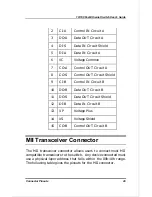
2
CI-A
Control IN Circuit A
3
DO-A
Data OUT Circuit A
4
DI-S
Data IN Circuit Shield
5
DI-A
Data IN Circuit A
6
VC
Voltage Common
7
CO-A
Control OUT Circuit A
8
CO-S
Control OUT Circuit Shield
9
CI-B
Control IN Circuit B
10
DO-B
Data OUT Circuit B
11
DO-S
Data OUT Circuit Shield
12
DI-B
Data IN Circuit B
13
VP
Voltage Plus
14
VS
Voltage Shield
15
CO-B
Control OUT Circuit B
MII Transceiver Connector
The MII transceiver connector allows users to connect most MII
compatible transceivers to the switch. Any device connected must
use a physical-layer address that falls within the 00h-10h range.
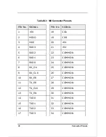
The following table gives the pinouts for the MII connector.

