22
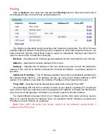
Routing
Click on
System
in the menu bar, and then click
Routing
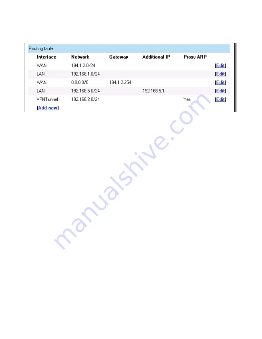
below it; this will provide a list of
all configured routes, and it will look something like this:
The Routes configuration section describes the firewall’s routing table. The DFL-700 uses
a slightly different method of describing routes compared to most other systems. However, we
believe that this method of describing routes is easier to understand, making it less likely for
users to cause errors or breaches in security.
Interface
– Specifies which interface packets destined for this route shall be sent through.
Network
– Specifies the network address for this route.
Gateway
– Specifies the IP address of the next router hop used to reach the destination
network. If the network is directly connected to the firewall interface, no gateway address is
specified.
Additional IP Address
– The IP address specified here will be automatically published on
the corresponding interface. This address will also be used as the sender address in ARP
queries. If no address is specified, the interface IP address of the firewall will be used.
Proxy ARP –
Specifies that the firewall shall publish this route via Proxy ARP.
One advantage with this form of notation is that you can specify a gateway for a particular
route, without having a route that covers the gateway’s IP address or despite the fact that the
route that covers the gateway’s IP address is normally routed via another interface.
The major difference between this form of notation and the form most commonly used is
there is no need to specify the interface name in a separate column. Instead, you specify the
IP address of each interface as a gateway.
Note:
Proxy ARP will publish the remote network on all interfaces (except WAN) if
enabled on the VPN tunnel.
Summary of Contents for DFL-700 - Security Appliance
Page 1: ...D Link DFL 700 Network Security Firewall Manual Building Networks for People 04 18 2005 TM ...
Page 102: ...102 5 Select Connect to the network at my workplace and click Next ...
Page 103: ...6 Select Virtual Private Network connection and click Next ...
Page 104: ...104 7 Name the connection MainOffice and click Next ...
Page 105: ...8 Select Do not dial the initial connection and click Next ...
Page 106: ...106 9 Type the IP address to the server 194 0 2 20 and click Next 10 Click Finish ...

