5 Configuration
D-Link Web Smart Switch User Manual
3
3
1
1
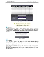
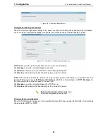
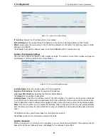
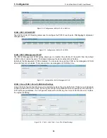
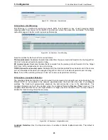
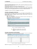
Figure 5.21 – System > IPv6 Route Settings
IP Interface:
Specify the IP interface which to be created.
Default Gateway:
The corresponding IPv6 address for the next hop Gateway address in IPv6 format..
Metric:
Represents the metric value of the IP interface entered into the table. This field may read a number
between 1 and 65535.
Click
Create
to accept the changes made, and click the
Delete
button to remove the entry.
System > IPv6 Neighbor Settings
The user can configure the Switch’s IPv6 neighbor settings. The Switch’s current IPv6 neighbor settings will
be displayed in the table at the bottom of this window.
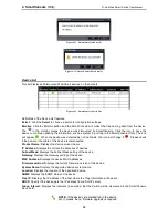
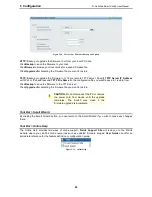
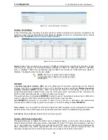
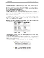
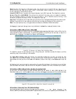
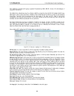
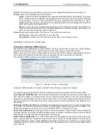
Figure 5.22 – System > IPv6 Neighbor Settings
Interface Name:
Enter the interface name of the IPv6 neighbor.
Neighbor IPv6 Address:
Specifies the neighbor IPv6 address.
Link Layer MAC Address:
Specifies the link layer MAC address.
Click
Apply
for the settings to take effect.
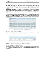
Interface Name:
Specifies the interface name of the IPv6 neighbor. To search for all the current interfaces
on the Switch, go to the second Interface Name field in the middle part of the window, tick the All check box.
Tick the Hardware option to display all the neighbor cache entries which were written into the hardware table.
State:
Use the drop-down menu to select All, Address, Static or Dynamic. When the user selects address
from the drop-down menu, the user will be able to enter an IP address in the space provided next to the state
option.
Click
Find
to locate a specific entry based on the information entered.
Click
Clear
to clear all the information entered in the fields.
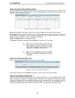
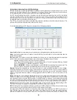
System > Password
Setting a password is a critical tool for managers to secure the Web-Smart Switch. After entering the old
password and the new password twice, click
Apply
for the changes to take effect.
Summary of Contents for DGS-1210-10P
Page 1: ......
Page 32: ...5 Configuration D Link Web Smart Switch User Manual 2 27 7 Figure 5 16 User Guide Micro Site...
Page 109: ......

