5 Configuration
D-Link Web Smart Switch User Manual
3
3
9
9
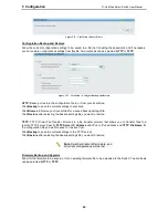
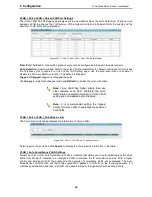
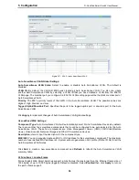
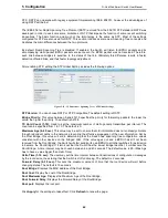
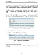
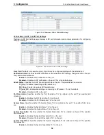
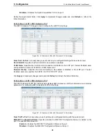
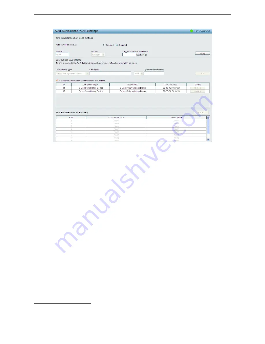
Figure 5.37 – VLAN > Auto Surveillance VLAN
Auto Surveillance VLAN Global Settings:
Auto Surveillance VLAN State:
Select to enable or disable Auto Surveillance VLAN. The default is
Disabled.
VLAN ID:
By default, the VLAN ID 4094 was created as Auto Surveillance VLAN. You also can create
another Auto Surveillance VLAN by selecting a VLAN ID that you have created a VLAN from the 802.1Q
VLAN page. The member port you configured in 802.1Q VLAN setting page will be the static member port of
Auto Surveillance VLAN.
Priority:
The 802.1p priority levels of the traffic in the Auto Surveillance VLAN. The possible values are
Highest, High, Medium and Low
.
Tagged Uplink/Downlink Port:
Specifies the ports to be tagged uplink port or downlink port for the Auto
Surveillance VLAN.
Click
Apply
to implement changes of Auto Surveillance VLAN global settings.
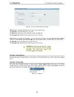
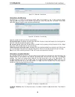
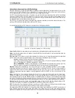
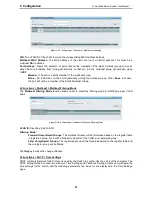
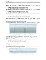
User-defined MAC Settings:
Component Type:
Auto Surveillance VLAN will automatically detect D-Link Surveillance Devices by default.
There are another five surveillance components that could be configured to be auto-detected by the Auto
Surveillance VLAN. These five components are
Video Management Server (VMS), VMS Client/Remote
viewer, Video Encoder, Network Storage
and Other
IP Surveillance Devices
.
Description:
Here to input the description for the component type.
MAC/OUI:
You can manually create an MAC or OUI address for the surveillance component. The maximum
number of user defined MAC address is 5. System will auto generate an ACL profile (Profile ID: 56) for all the
Auto Surveillance VLAN rules.
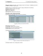
Click
Add
to create a new surveillance component and
Refresh
to refresh the Auto Surveillance VLAN
summary table.
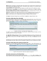
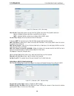
L2 Functions > Jumbo Frame
D-Link Gigabit Web Smart Switches support jumbo frames (frames larger than the Ethernet frame size of
1536 bytes) of up to 10,000 bytes (tagged). Default is disabled, Select
Enabled
then click
Apply
to turn on
the jumbo frame support.
Summary of Contents for DGS-1210-10P
Page 1: ......
Page 32: ...5 Configuration D Link Web Smart Switch User Manual 2 27 7 Figure 5 16 User Guide Micro Site...
Page 109: ......

